

Photovoltaic modules and systems operate at voltage levels that are potentially dangerous to human safety. In photovoltaic modules and installations, there is great concern about providing electrical insulation between the active parts (which produce electrical potentials) and the parts that will have direct contact with people (frames, cables, junction boxes and glass).
An important measure of the electrical insulation of a photovoltaic module is its insulation resistance. Insulation resistance is analyzed in certification laboratories and is one of the main safety requirements for the approval of photovoltaic modules. This test aims to analyze the leakage current that arises with the application of a high voltage, consequently verifying the insulation resistance of the module [Hernandez, 2010].
The high voltage insulation resistance test is carried out in Brazil as per Ordinance 004/2011 of the INMETRO (National Institute of Metrology, Quality and Technology), in accordance with the procedures listed in the international standard IEC 61215. INMETRO ordinance 004/2011, in accordance with IEC 61215, regulates the certification tests of photovoltaic modules in Brazil, in order to grant the qualification label and therefore allowing the insertion of the equipment in the Brazilian market.
Among the mandatory tests for the qualification of photovoltaic modules, it is necessary that they pass two tests related to insulation resistance, in accordance with the IEC 61215 nomenclature: 10.3 – Dry insulation test and 10.15 – Leakage current test with humidity. The first will be covered in more detail in this article, while the second will be presented in a future article.
Although the insulation of a photovoltaic module plays a fundamental role in preventing electrical shocks, the insulation of the active parts also fulfills the objective of preventing the photovoltaic cells from coming into contact with the external environment, preventing their contact with air, water and other impurities and their consequent degradation process.
According to the premise of most module manufacturers on the market, modules are developed to operate for 25 years, therefore it is essential that all potential risks to the modules' durability are mitigated, whether through mechanical or electrical construction aspects.
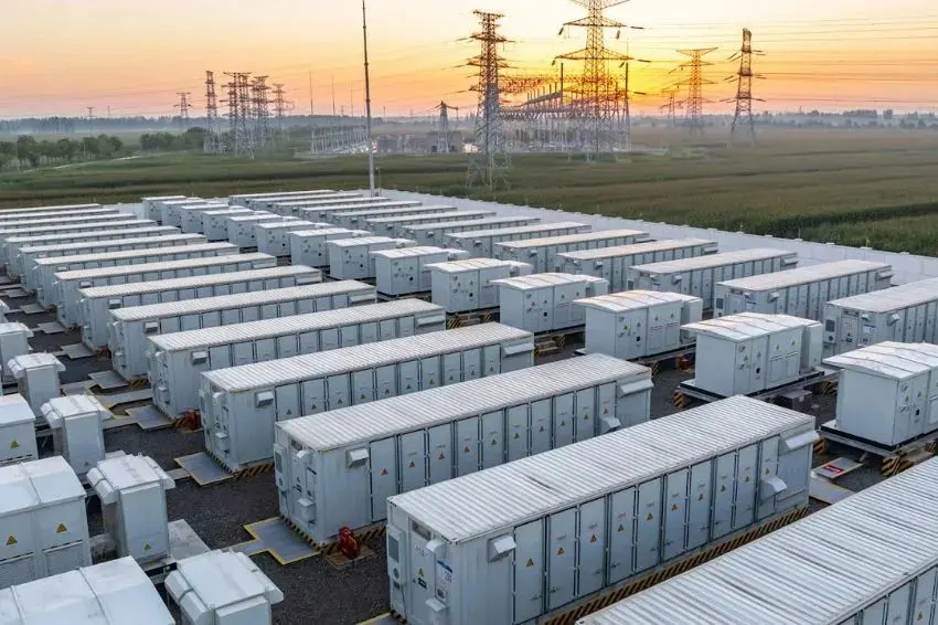
Electrical insulation in photovoltaic plants
Electrical insulation testing is also carried out on photovoltaic systems in the field. Laboratory and field test procedures differ, but the objective is the same: to test the safety of the electrical insulation of the photovoltaic system.
While the laboratory test tests the electrical resistance between the electrical terminals of a single module and its metal frame, the field test measures the electrical resistance between the terminals of the photovoltaic string and the installation's ground bus (to which the frames must be connected). of all modules).
In Brazil, the ABNT NBR 16274:2014 standard is used to perform electrical resistance tests in the field, which concerns the strings of photovoltaic systems. In the commissioning of photovoltaic plants, ABNT NBR 16274:2014, currently under review, specifies two methods for testing the insulation resistance of the photovoltaic array.
The standard states that in situations where the results are questionable, a humidity test must be performed, in line with what is performed in laboratories, although the approval parameters are different. The subject of insulation testing in the commissioning of photovoltaic systems is covered in greater depth in the article published in Canal Solar: “Insulation resistance test in photovoltaic systems”.
PV module components
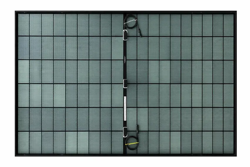
The figure below shows the components of a typical photovoltaic module, with front glass and rear plastic sheet (back sheet). The electrical components of the modules are encapsulated between layers of plastic and glass. The encapsulation is carried out by a vacuum lamination process, which should result in a hermetic packaging free of air inside.
The encapsulation of electrical components aims to provide mechanical stability and isolation of electrical parts from the external environment, especially preventing photovoltaic cells from suffering degradation due to contact with air or water.

In the figure above we see how the following components of a typical photovoltaic module are structured:
- Backsheet: In modules like standard, backsheet It is composed of a polymeric material such as Tedlar (polyvinyl fluoride), which appears as a white plastic. It makes up the cell isolation structure with the external environment at the back of the module;
- EVE: Ethylene-vinyl-acetate is an encapsulating thermoplastic, responsible for electrically and mechanically isolating photovoltaic cells from the external environment. As it is a polymer with excellent insulation capacity and has a high degree of optical transmissivity, it is the most widespread material among the modules currently on the market;
- Cells. Cells.: Photovoltaic cells connected using metal ribbons (ribbons) and welds;
- Frame: Photovoltaic module frame, usually made of aluminum;
- junction box: Photovoltaic module junction box, where the bypass diodes and electrical terminals of the photovoltaic cells are housed.
Insulation resistance modeling
From the composition of a typical photovoltaic module it is possible to model the insulation resistance [Roy, 2015].

From this modeling it is possible to note that the insulation resistance will be calculated from the resistance resulting from the parallel between R1, R2, R3 and R4 with the resistances R5, R6, R7 and R8. It should be noted that insulation resistance does not take into account photovoltaic cells, bypass diodes or solar cables, due to the fact that they are active and conductive parts.
Regarding the contribution of each of the resistances, we have the following orders of magnitude:
- R1 and R8: milliohms [mΩ];
- R2, R3 and R7: megohms [MΩ];
- R4 and R5: megaohms to teraohms [MΩ – TΩ];
- R6: teraohms [TΩ].
The equivalent resistance between the terminals shown in the previous figure can be calculated from the following equation:
Req = (R1+R2+R3+R4)*(R5+R6+R7+R8)/(R1+R2+R3+R4+R5+R6+R7+R8)
This resistance usually has a dimension of gigaohms [GΩ], according to [Roy, 2015].
Consequences of poor insulation of active parts
-
leakage current
According to the IEC 61215 standard, the module will have its insulation resistance approved if the product of the insulation resistance and its area is greater than or equal to 40 MΩ.m2. This resistance must be measured between the short-circuited terminals and the module frame, as shown in Figure 2.
Carrying out a simple calculation, according to Ohm's law, the leakage current associated with this test must be less than 1 mA. It is worth mentioning that the insulation resistance in the field takes several other factors into its composition, as well as the possibility of current leakage through conduits and cable trays.
Below is Table 1 of the ABNT NBR 16274:2014 standard, which shows the test parameterization and the minimum values expected for the insulation resistance test on photovoltaic strings.
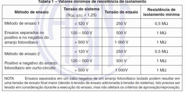
In this scenario, we have two distinct values of the resistance parameter. As the modules are validated in laboratories, it is assumed that the insulation resistance, when newly manufactured, is at least minus 40 MΩ.m2
Since the modules generally have an area of approximately 3,1 m2, the insulation resistance (measured between the two terminals and the frame) is at least 13 MΩ. Secondly, the modules in the field are subject to different environmental conditions, such as higher temperatures and potentially higher humidity, which directly affects the insulation behavior of the modules.
From a safety point of view, the 1 mA leakage current does not present major health risks if any individual is subjected to it. However, the aging of the photovoltaic module can reduce resistance and increase this leakage current over time.
-
Acceleration of degradation processes of photovoltaic modules
A low insulation resistance of the photovoltaic module results in a higher amplitude of the leakage current that circulates in the inactive parts (non-electrical conductors), accelerating the degradation processes. The increase in the leakage current (or the insulation failure) intensifies degradation phenomena such as the PID effect [Vinturini, 2919] and corrosive processes that degrade the photovoltaic cells [Li, 2018].
Regarding the constructive isolation of the photovoltaic module, poor isolation of the active parts from the external environment causes the cells and encapsulating media to come into contact with impurities that accelerate the degradation processes, which can generate bubbles, delamination, yellowing of the cells, degradation of welds and consequently, generating mismatch in strings [Manganiello, 2015][Sako, 2019]
Electrical insulation resistance test in dry conditions according to IEC 61215-2021
According to the standard, the purpose of this test is to determine whether the live parts of the photovoltaic module are sufficiently isolated from the accessible parts. Since it is a test that covers all components of the photovoltaic module, it serves as a reference for the others listed in the IEC.
In other words, before and after the module undergoes other degradation tests, such as thermal stress, salt spray, freezing, UV (ultraviolet) degradation, mechanical stress, among others, its insulation resistance is evaluated, which increases the importance of this test. As a prerequisite for the test, the acceptable ambient temperature for the test is 25 ºC, with variations of up to ±5 ºC, and the relative humidity of the ambient air must be less than 75%.
The equipment required for the test is: (a) DC high voltage source with current limiter, capable of applying the voltages necessary for the test and (b) instrument capable of measuring insulation resistance. A piece of equipment that incorporates both functions, known as a “hipot” tester, is shown in the figure below.

Insulation testing procedures per IEC 61215:2021
Initially, it is necessary to short-circuit the photovoltaic module terminals to the positive terminal of the “hipot” using a Y pigtail, as shown in Figure 4.

The negative terminal of the “hipot” tester must be connected to the metal frame of the photovoltaic module under test, as shown in Figure 5. In situations where the sample does not have a frame, such as in some modules of the type double glass, it is necessary to cover the edges with aluminum foil and then connect the negative terminal to this auxiliary structure.

With the test assembly completed, the “hipot” tester must be configured according to the parameters required by standard and according to the module area and the maximum system voltage (generally 1000 V or 1500 V). The dimensions of the module and its voltage class are found on the label that must accompany the product.
The first insulation test is a pre-conditioning process, where a voltage Vtest equivalent to 1000V + 2*Vmax system is applied, that is, for 1000 V modules, a voltage of 3000 V must be applied, while for 1500 V modules the voltage of 4000 V must be applied.
The Hipot tester must be configured so that the voltage rise does not exceed a rate of 500 V/s until the specified test voltage is reached. Preconditioning occurs during the 1-minute period under the test voltage. For the module to pass preconditioning, two conditions are essential:
- The dielectric material cannot suffer rupture, that is, the EVA cannot suffer visible damage.
- The resistance measured between the terminals cannot be less than the Risol value = (40 M.ohms/m2) / module area.
For the last condition to be satisfied, the “hipot” tester is configured so that the test is interrupted (and consequently failed) with a leakage current greater than Ifuga = Vteste / Risol.

Then a second test is performed, with the same failure condition assumptions. In this second case, however, the photovoltaic module is exposed to a voltage equal to its maximum system voltage for 120 seconds.

If the photovoltaic module does not reach the leakage current limit established at the beginning of the test, it can be considered approved. In INMETRO certification, which currently complies with ordinance 004/2011, the insulation test is the first to which the module is subjected (after the initial stage of stabilization in sunlight).
Once this test is approved, the module is subjected to the following tests. INMETRO ordinance 004/2011 follows the same parameters and procedures specified in the IEC 61215 standard. The IEC 61215 standard includes a large set of tests that cause accelerated aging and degradation of photovoltaic modules: salt spray (saline environment), damp heat (humid heat), exposure to UV (ultraviolet) light, mechanical load, thermal cycle (heating and cooling) and humidity freeze (freezing in a humid environment).
These tests intensify degradation processes that would occur naturally throughout the useful life of the photovoltaic module, which is why the electrical insulation test is carried out before and after each of these tests.
Conclusion
The insulation resistance test outlined by IEC 61215, and adopted by INMETRO ordinance 004/2014, establishes the procedures necessary to measure the insulation capacity of a photovoltaic module in dry conditions. The insulation resistance of a photovoltaic module is provided by the layers of insulating materials used in its manufacture, with EVA being the main material contributing to this insulation.
According to the IEC 61215 standard, the minimum insulation resistance for module approval is 40 MΩ.m2. Values below are considered potentially dangerous in relation to leakage current, which could cause electric shocks to the individual handling the module.
In addition to electrical insulation, photovoltaic cells need to be very well sealed from the external environment, as their contact with water, air and impurities can accelerate degradation processes. The electrical insulation test ends up being, indirectly, a measure of the quality of the encapsulation of the internal components, whose quality is essential for extending the useful life of the module.
References
- [Hernandez,2010] Hernández, JC, Vidal, PG, & Medina, A. (2010). Characterization of the insulation and leakage currents of PV generators: Relevance for human safety. Renewable Energy, 35(3), 593–601. https://doi.org/10.1016/j.renene.2009.08.006
- [Roy,2015] Roy, J. N. (2015). Modeling of insulation characteristics of Solar Photovoltaic (SPV) modules. Solar Energy, 120, 1–8. https://doi.org/10.1016/j.solener.2015.06.036
- [Vinturini, 2919] Mateus Vinturini, The PID effect and its action on photovoltaic modules, 2019. https://canalsolar.com.br/o-efeito-pid-e-sua-acao-sobre-os-modulos-fotovoltaicos/
- [Li, 2018] Li, J., Shen, Y. C., Hacke, P., & Kempe, M. (2018). Electrochemical mechanisms of leakage-current-enhanced delamination and corrosion in Si photovoltaic modules. Solar Energy Materials and Solar Cells, 188(May), 273–279. https://doi.org/10.1016/j.solmat.2018.09.010
- [Manganiello, 2015] P. Manganiello, M. Balato, and M. Vitelli, “A Survey on Mismatching and Aging of PV Modules: The Closed Loop,” IEEE Trans. on Indus. Electron., vol. 62, pp. 7276–7286, 2015.
- [Sako, 2019] Sako, EY, Lucas De Souza Silva, J., Bastos Mesquita, D. De, Espino Campos, R., Moreira, HS, & Gradella Villalva, M. (2019). Concepts and Case Study of Mismatch Losses in Photovoltaic Modules. 2019 IEEE 15th Brazilian Power Electronics Conference and 5th IEEE Southern Power Electronics Conference, COBEP/SPEC 2019, 1–6. https://doi.org/10.1109/COBEP/SPEC44138.2019.9065311


Answers of 4
In addition to these tests, what are the tests that are mandatory under Brazilian standards (Factory tests / Field tests)?
Good afternoon, Carlos, how are you?
According to NBR 16274 – “Grid-connected photovoltaic systems – Minimum requirements for documentation, commissioning tests, inspection and performance evaluation”, the commissioning tests are:
– Category 1:
Testing the AC circuit(s) according to the requirements of IEC 60364-6
Continuity of earthing and/or equipotential bonding conductors
Polarity test
Junction box testing
Current test of the photovoltaic series(s) (short circuit or operational)
Open circuit voltage test of photovoltaic array(s)
Functional assays
Insulation resistance test of DC circuit(s)
– Category 2:
IV curve test of the photovoltaic series(s)
Inspection with infrared camera
Is there a way to perform this test in the field?, with the system installed.
excellent material.
It catches my attention that even the hipot test is Chinese.
how much technological dependence on china.
It's a shame that we don't have national equipment.
prof. Carlos Argolo Ph.D.