
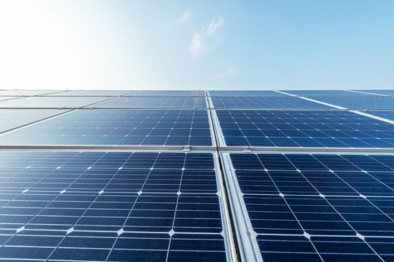
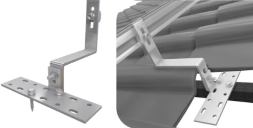
There is a wide range of types of roofs where solar systems are usually installed, from residential ceramic roofs on roofs zipped metal of large warehouses. Naturally, many solutions will emerge fixing modules to roofs and which, given the specificity of each application, are not interchangeable.
As they are not interchangeable, situations may arise where the structure used is incompatible with the roof and with the module's ventilation and warranty requirements. In this article, we will study technically and commercially the implications of using structures that do not allow the minimum spacing between module and roof recommended by manufacturers.
Technical analysis
Temperature and power relationship
All modules lose power as their cells heat up. This data is described in the data sheet by the power coefficient Pmpp, usually described in percentage of power per degree ºC of cell temperature above the STC test temperature (25 ºC).
Due to its thermal behavior, it is desirable that the module works at the lowest possible temperature. As it is not feasible to install active ventilation systems for the modules, we depend on natural passive ventilation to cool the module. It is then expected that the module installation method will have an effect on its cooling.
The calculation of heat dissipation is complex to be described in a simple equation or to be calculated manually. However, using software it is possible to estimate the loss of generation due to the thermal effect of installing a module with a distance from the roof (recommended by most manufacturers of at least 10 cm) or without any distance at all.
The table and figures below show the results of simulations with the software PVSyst, for a 4.8 kWp residential application with 4 kW inverter in the city of Montes Claros (MG), with and without distancing the modules from the roof.
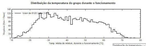
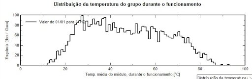
The energy simulation results corroborate the temperature effect seen in the figures above:
Table 1 – Simulation results
| Situation | Total energy generation | Thermal losses – Energy | Predicted maximum temperature |
| With spacing | 8121 kWh | -8,8% | 76ºC |
| No spacing | 7841 kWh | -12% | 90ºC |
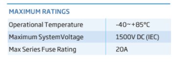
The maximum temperatures may even be higher than the maximum working temperatures described in the data sheets, thus invalidating the warranty and putting the health of the modules at risk.
Temperature of cables, microinverters and accessories
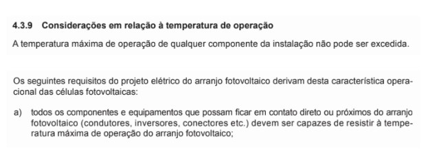
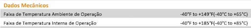
Components close to the modules, such as cables, microinverters, clamps, adhesives and conduits that come into contact or are close to the modules, must normally withstand the same maximum working temperature as the module, as detailed in section 4.3.9 of the NBR 16690 standard.
As seen in item 1) above, the modules can reach up to 90 ºC when mounted very close to the roof. In addition to making access to the cables difficult and increasing the chance of cables breaking during the assembly process, this solution may cause overheating in the components shown, which greatly increases the probability of failure and may invalidate your warranties.
Fire resistance rating
The modules are tested to have a minimum fire resistance (as detailed in the standard IEC 61730-2). In some parts of the world there is a mandatory minimum level of fire resistance for all building components.
Most manufacturers only guarantee the minimum level of fire protection when all assembly requirements described in the module installation manual are met. It is only possible to guarantee that the module has this fire protection if the recommendations in the product installation manual are met.
Installation and warranty manual analysis
All module manufacturers have installation manuals for their products with instructions and mechanical limits for module assembly. The wind load resistance rating, product durability and fire resistance depend on the correct installation of the module.
Therefore, it is common for module manufacturers to invalidate the product warranty in situations where the module installation did not meet the installation requirements. As an example, the table below shows recommendations from 3 different manufacturers regarding roof spacing.
Table 2 – Analysis of module installation manual for 3 different manufacturers
| Manufacturer | Original text | Translation |
| “TS” | 6.1 MOUNTING METHODS PV
A clearance of at least 115mm(4.5in) (recommended) is provided between the module's frame and the surface of the wall or roof. If other mounting means are employed this may affect the UL Listing or the fire class ratings. |
6.1 PV mounting methods
A spacing of at least 115mm must be provided between the module frame and the surface of a wall or roof. If another type of mounting is applied, this may affect the UL fire resistance rating. |
| “JS” | 3.5 Fire Safety
In order to maintain the fire class rating, the distance between the module's frame surface and roof surface shall be at least 10 cm.
5. Mechanical Installation
When the modules are supported parallel to the surface of the building wall or roof, a minimum clearance of 10 cm between the modules frame and the surface of the wall or the roof is required to allow air to circulate behind the modules and to prevent wiring damage . |
3.5 Fire safety
For the module to maintain its fire rating, the distance between the module frame and the roof surface must be at least 10 cm.
5. Mechanical Installation
When modules are mounted parallel to the surface of a wall or roof, there must be a minimum spacing of 10 cm between the module frame and the wall or roof surface to allow air passage behind the module and to prevent damage to the cabling . |
| “JK” | 2.2.2 Site Selection
When the modules are installed on the roof, they must be separated from the roof by more than 10cm to facilitate air circulation and heat dissipation. |
2.2.2 Site selection
When modules are installed on the roof, they must be separated from the roof by more than 10 cm in order to facilitate air circulation and heat dissipation. |
Analyzing the manufacturers' warranty terms, any deviation from the assembly in relation to the installation manual may void the warranty.
Table 3 – Analysis of warranty terms
| Manufacturer | Original text | Translation |
| “TS” | 4) Exclusions and Limitations
The aforementioned “Limited Warranty” does not apply to any Products which have been subjected to
b) Failure to comply with the requirements of TS user manual |
The aforementioned limited warranty terms do not apply to products that:
b) They do not comply with the TS requirements described in the user manual |
| “JS” | 3. Exclusions and Limitations
(b) The Limited Product Warranty and Limited Peak Power Warranty shall not apply to MODULES which have been subject to: Alteration, improper installation or application; |
3. Exclusions and limitations
(b) The limited product warranty and peak power warranty do not apply to modules that have been subject to:
Improper alteration, installation or operation |
| “JK” | 7. EXCLUSIONS. This Limited Warranty is subject to the exclusions set forth in this Section 7. The Warranties shall not apply to any Module which has been:\
(g) used in a manner inconsistent with the version of Jinko Installation Manual available on the date the Module is manufactured. |
7. Exclusions.
The limited warranty is subject to the exclusion set out in section 7. The warranty does not apply to modules that:
(g) were used in ways inconsistent with the version of the JK installation manual available on the website at the date of product manufacture. |
Conclusion
There is no inherently wrong or bad type of structure. There are misapplications. The mistaken application of a structure in a way that is not compatible with the requirement for minimum distance between the module and the roof may result in loss of generation due to the temperature effect and may also result in the loss of the product warranty.
O installer should never ignore the module installation manual, as failure to observe an item may render the manufacturing warranty and potency warranty invalid.


10 Responses
The best place to place photovoltaic panels is on the ground or on top of roofs, such as a house, shed, etc. Note: We have stakes or concrete blocks measuring 1.83 cm and 1.30 cm for the ground, good for maintenance and changing plates, etc.
I have noticed that the distance between the roof and solar panels varies depending on the type of roof, zinc approximately 5 cm and ceramic approximately 10 cm…
Is it possible to increase the distance, say 20 ~ 30 cm or more, guaranteeing the performance of the plates and without compromising the safety of the panels (increasing the number of and more resistant fasteners) in relation to unusual winds that could make the panels fly away?
Good afternoon, Mario, how are you? Firstly, in every project it is ideal that you carry out a study on the wind isopleths of the location where the project will be installed, to know which structure to use, and on the distance from the module. that he must be
Thank you very much for sharing this information. As the temperature in a photovoltaic panel is very closely related to the conversion efficiency, I believe that we also have to explore the minimum distance “between” panels, to facilitate the natural convection of ventilation air. You usually see strings with panels practically glued together. Those located higher on the roof receive hot air heated from panels mounted in lower positions. Leaving gaps “between” panels to facilitate the exit of hot air and increase the flow of natural convection can be a good solution, when the roof has physical space. They also allow access for easier cleaning. So far I haven't been able to find any references on this subject. Here is a suggestion for investigation. Grateful
My plant was correctly assembled in 2019, complying with the minimum limit of 10 cm of tile, but in 2021, with the roof facing North to improve the system's generation capacity, the integrator lowered it to zero, and the roof is thermal tile, where it said it had more safety at the expense of strong winds, however, after installation I was worried about the fact that the panels were so close to the tiles and that's when I started researching the subject and found the articles that say when there is a minimum ventilation space, that's when I hired a new technician and redid the arrangement again, respecting the minimum space of 10 centimeters. I would like to report the lack of information on the part of the integrators that caused double losses. “FIRST in not asking about roof positions SECOND in application outside the manufacturer's standards.
Good morning. The issue is delicate, however, not only the installer has this responsibility for correct positioning of the installation. Demand in the market grows every day and there are several companies testing new structures. I understand, however, that this responsibility for correct distancing lies with the company that supplies the solar kit and not the installer. As an installer, I always use the material that is given to me when I decide on the type of roof.
Excellent content thank you!!
We appreciate the recognition, Renato!
Very good article.
Congratulations!
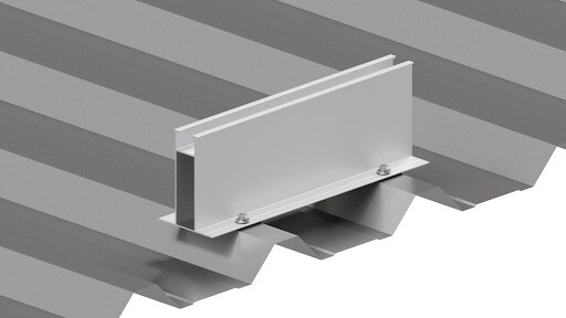
There are many companies using the mini rail without the support, on metal roofs, I believe it will cause damage to the modules.