

The analysis of faults in electrical networks is an essential task to ensure the safety of electrical systems and the continuity of energy supply. The correct identification and classification of faults allows electrical protections to operate selectively, isolating only the area affected by the fault, thus avoiding damage to equipment and people.
The Ampère Professional 2023 software, from Electro Graphics, offers a complete tool for analyzing faults in electrical networks. The software allows you to calculate the current flows that feed a fault, study their directions and magnitudes, and analyze various problems, such as the contribution of a fault that a photovoltaic plant can generate on the grid.
Furthermore, the Ampère Professional 2023 software allows you to check how an asymmetrical fault propagates in the network, also considering the presence of star-delta transformers.
The software also allows you to control the operation of the 67 phase directional protections, being able to analyze which currents are controlled and which adjustments must be made.
The software has a simulator that allows you to define a fault at any point in the mesh. You can decide whether this fault occurs upstream or downstream of the selected point, whether it is subtransient or permanent, and which conductors it involves.
With Ampère Professional 2023 software, electrical network designers can consciously evaluate fault situations in the most complex electrical networks in order to implement the correct solution for optimal system operation.
Foul simulator
The ANSI 67 panel, of the advanced Directional Protections function, allows you to define a fault at a point in the mesh. You can decide whether it occurs upstream or downstream of the selected user, whether it is subtransient or permanent, and which conductors it involves (the type of fault depends on the user's electrical circuit, including the possibility of ground currents).
Below you can view the commands present on the panel:
Fault flow analysis: activates fault current analysis, enables commands and displays fault currents. It is necessary to perform a preliminary network calculation to start the functionality.
Link missing to user: the selected user becomes a permanent point of a fault; Locking the fault point is useful for analyzing the portion of fault currents that pass through other users, who may be “distant” along the loop, allowing corrections or modifications for other users without changing the fault conditions.
Transient and fault point: The drop-down list allows you to choose between five different fault types, combining the transient period and the fault point. The lifetime of an electrical fault is typically divided into three distinct intervals: subtransient, transient, and permanent. The software handles subtransient and permanent. By fault point we mean the terminals upstream or downstream of a user.
Type of fault: the box contains the name of the user with the fault and a grid with the six types of fault that can be studied, which are enabled according to the type of circuit and the presence of earth.
List of directional protections: If present on the network, the list shows all protections with directional function 67, with information regarding the operating status according to the selected fault point.
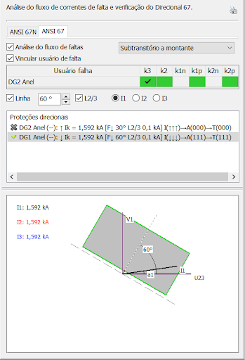
Representation of Fault Currents/ANSI 67: the graph offers the representation in modulus and phase of the phase and neutral currents of the selected user (Analysis point P), seen after a fault at point F. If the user has protection 67, the graph displays its main properties: intervention sector (line/bar), characteristic angle, trigger logic.
Given a design, select a study point F to simulate a fault, for example, three-phase subtransient upstream.
Perform a design recalculation to update the fault currents, information needed to perform the fault current flow simulation. Select the Fault Flow Analysis command and, on the Mesh, the fault point F will be indicated by a yellow symbol that resembles an electric arc.
The software provides the values in modules and the direction of the currents that supply the fault and that pass through the users in question (point P).
These values are represented with dedicated labels in the data field, which appears next to each user in the mesh.
Furthermore, for the examined and selected user, the ANSI 67 panel displays the vectors of the phase currents that constitute the fault, in magnitude and angle in relation to the reference voltage V1 of phase 1.
Contribution of lack of photovoltaic plant
The Ampère software has always considered the contribution of photovoltaic generators in the calculation, which must also be added to that of engines, storage systems, etc. Therefore, the fault current at point F can be the sum of several elements, each with its own “weight”.
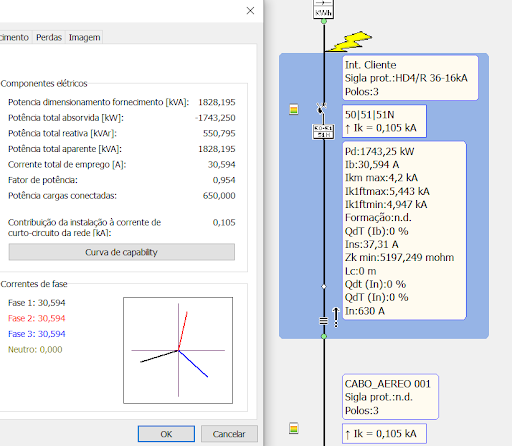
The function of Analysis Fault monitoring allows you to visualize current flows and understand fault sources quickly.
In particular, when choosing the first user connected to the power supply as the fault point F, the user will inform the contribution of the generators, a value that coincides with that shown in the Supply window with the name Installation contribution to the network short-circuit current.
Attention: The fault flow analysis is carried out considering the Standard method as the calculation method (all faults are far from the sources).
Asymmetrical fouls
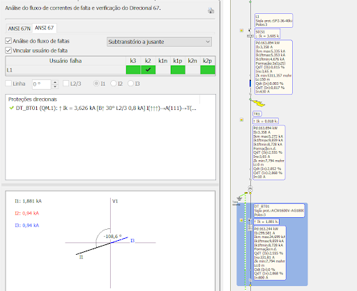
Fault current analysis can be useful for studying asymmetric faults and the currents seen by protections placed on the opposite side of a transformer.
The typical case of protection with two transformers (Dy) in parallel. For a two-phase fault on the primary of a transformer, a distribution of currents in the 2-1-1 relationship is found on the secondary side.
The figure on the side reproduces the situation described, with currents circulating in the secondary with a value of 1881-940-940 A. To better exemplify the situation, at the end of the article there is an example with two transformers in parallel demonstrating the scenario.
The example described is important in the management of entry protections, as Directions 67 can intervene, and in the next point we will analyze this situation further.
Phase 67 directional protections
Maximum directional phase current ANSI Code 67 is a protection function supported by the Ampère software and, like the other types, is managed in Devices, Protection Calibrations in the Additional ANSI Functions field.
This protection is three-phase and involves a maximum phase current function associated with direction detection; is energized if the phase overcurrent function in the selected direction (line or bus) is triggered by at least one of the three phases (or two phases of three, depending on the parameterization).

The alarm linked to the protection action indicates the missing phase(s). The protection is timed and the time can be defined or independent time.
Attention. The software only provides the indication relating to the alarm, the triggering in relation to the intervention limit is not managed at the moment.
Let's analyze how a 67 protection works with the help of the figure to the side. The direction of the current (I1) is determined by measuring its phase (a1) in relation to a polarization quantity (U23), which is the phase-to-phase voltage in quadrature with the reference voltage of the phase under examination (V1).
The part of the network downstream of the protection is defined as Line Zone / Line Direction / Forward.
The part of the network upstream of the protection is defined as Bus Zone / Bus Direction / Backward. The plane of the current vectors of a phase is divided into two half-planes corresponding to the Line Zone and the Bus Zone. The characteristic angle (30°) is the angle of the perpendicular to the boundary line between these two zones and the amount of polarization (U23).
Strain memory hypothesis
If all voltages disappear when a three-phase fault occurs near the bus system, the voltage level may be insufficient to detect the fault direction.
The protection then uses a voltage memory to reliably determine direction. The Ampère software works considering that the 67 directional protection has this memorization function.
Protections 67 can work in two different ways to determine the area of intervention.
[Line Zone/Bus Zone]: the box must be selected if the protection uses the Line/Bus + characteristic angle logic, otherwise it only controls the characteristic angle: 0°-90° or 270°-359° Line zone; 91°-269° Bus zone.
Operation logic 2/3: In some cases, it is advisable to choose a two-phase or three-phase intervention logic.
Example of Medium Voltage
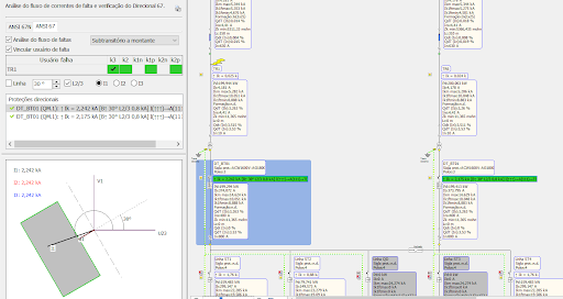
In the situation analyzed below, we see the behavior of two directional protections 67 used to protect a section of network managed in a ring; following a three-phase fault at a point F outside the ring, one protection goes into alarm (green color) and the other does not act (gray color).
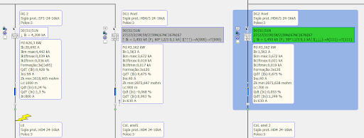
Let's analyze the values of directional protections reported on the Mesh labels and in the ANSI 67 panel list.
Alarm protection: the down arrow indicates the direction of the fault current, with a value of 1.507 kA. The data inside the brackets [F↓ 30° L1/3 0.1 kA] are the protection settings and, in order, the Line Zone (F) setting, a characteristic angle of 60° and operating logic 1/3 (a phase of three).
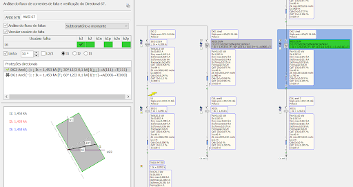
Below is the list of phase current directions according to the limit line I(↓↓↓): in this case they are all in the direction of the Zone line.
Finally, the alarm status is shown with the list of phases that would trigger protection A(111), that is, all three phases, and the frame turns green indicating the activation of the protection alarm.
Alarm-free protection: the upward arrow indicates the direction of the fault current, with a value of 1.507 kA. The data within the brackets are the protection settings and, in order, the Line Zone (F) setting, a 60° characteristic angle, and operating logic 2/3 (two of the three phases).
Below is the list of phase current directions according to the limit line I(↑↑↑), and in this case they are all in the direction of the Bus Zone. Finally, the alarm status is shown with the list of phases that would trigger protection A(0), that is, without phase, and the frame turns gray indicating that there is no alarm.
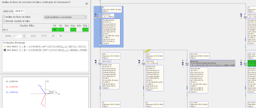
Example of parallel transformers
Let's return to the problem from the previous point Asymmetrical fouls. The network is powered by two transformers in parallel, which must be protected against faults within the ring, avoiding unwanted openings.
A critical case is the management of a two-phase fault on the primary side, as can happen if two phases accidentally come into contact due to a foreign body.
This fault can send an alarm to both directional protections positioned on the input side, as shown in the figure.
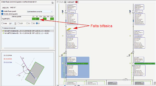
To section the section of the left branch line, only the ReléBT1 user must intervene.
With the settings defined [B↑ 30° L1/3], phase 1 and phase 3 agree and disarm protection A(101). In ReléBT2 protection, on the right, with settings [B↑ 30° L1/3] equal to the previous one, phase 2 agrees in direction, and with operating logic L1/3 the alarm is triggered, an undesirable situation.
For this user, operational logic comes in handy, because by placing it in the L2/3 position and requesting at least two phases accordingly, the objective of creating the necessary selectivity is achieved.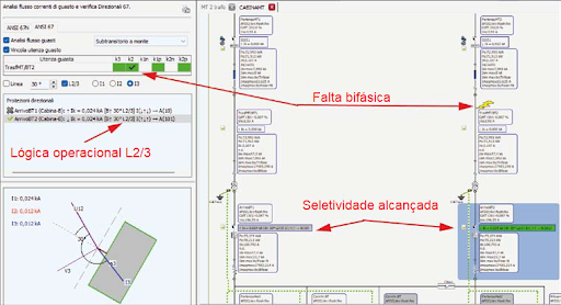
As the network is symmetrical and the fault can occur in the second transformer branch, both protections must be set to L2/3 operational logic. The figure displays what is described.
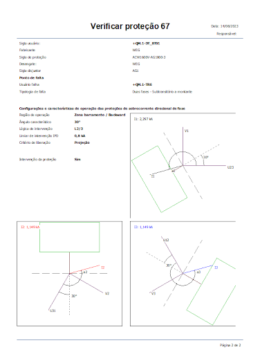
Printing reports
The ANSI 67 panel has the Print Management function, useful for attaching the study of directional protections 67 to the project.
To activate the prints, a user with protection 67 must be selected, and the print will report the complete analysis in the three phases along with the final result.
The opinions and information expressed are the sole responsibility of the author and do not necessarily represent the official position of Canal Solar.