
During negotiations for the acquisition of a photovoltaic system, it is common for the customer to create great expectations regarding their new acquisition, especially considering the promise of financial savings from “energy from the Sun”.
Unfortunately, it is possible that the system will not meet expectations due to the low performance of the photovoltaic solar generator, that is, the amount of energy that was “forecast” or promised to the customer during the commercial negotiation stage will not be generated.
It is known that to achieve success in a photovoltaic project a detailed study of the customer's consumption profile is necessary, in addition to all technical care in the design and execution of the photovoltaic system.
In summary, the final performance of the photovoltaic system can be affected by one of the following phases that make up a project:
- Sizing: During the negotiation phase with the customer and preparation of the commercial proposal, sizing must be carried out with correct assumptions, through a thorough analysis of the customer's energy bills and with the help of sizing and simulation tools for photovoltaic systems ( like the PVSyst).
- Project: The technical design of the photovoltaic solar generator must be carried out in accordance with good photovoltaic engineering practices, respecting the relevant technical standards. Errors in the electrical cabling structure, in the organization of strings It is arrays and other aspects can ruin everything. Typically, the lack of training of companies in the solar sector is what most affects this project phase.
- Installation: It’s not enough to have a well-done project – it needs to be well executed. Poorly organized cables, poorly made connectors and installers who step on modules are just some of the problems encountered in solar installations. Here too, the training of the supplier company is fundamental to the success of the project.
Photovoltaic system sizing
At this stage, the size (power) of the system that will be installed and the resources to be used are defined – inverters, microinverters, optimizers, type and number of modules, etc.
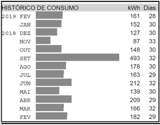
At this stage, it is necessary to analyze the consumer's average monthly consumption based on at least the previous 12 months, in order to design an appropriate system so that the customer pays the lowest amount possible on their next energy bills.
Very calm at this time! Many solar companies, eager to close the deal, promise customers the world. Some customers will close the deal without question, but the headache may come later if the promise made does not come true.
The best thing to do is to analyze the customer's historical consumption and use tools (such as PVSyst) to correctly size the system. Even so, it is important to inform the client (and preferably establish this in the contract) that, despite the best engineering practices used in sizing the solar system, the result may vary depending on the local climatic conditions.
Absolute generation certainty will never be possible. The important thing is that the system is correctly sized, with correct technical foundations, and that the customer receives information with the maximum transparency possible.
Technical project
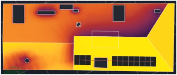
After the commercial negotiation phase, the technical project stage will begin. At this point, it is necessary to pay attention to the characteristics of the installation site, such as available area, inclination and azimuth, possible interference with the potential for shadow projection, in addition to the solarimetric information of the region where the system will be installed.
When analyzing all areas available for installation, it is necessary to identify which regions of the roof have the best generation results, something that can be verified with sizing and simulation tools such as PVSyst.
The best way to interconnect modules must also be taken into account in order to maximize the generation of the photovoltaic system. A very common mistake made by solar energy companies, due to lack of technical knowledge, is the interconnection of modules located on different roof areas within the same roof. string (set of modules in series). This practice, in addition to not complying with photovoltaic system design standards, compromises energy generation and also the safety of photovoltaic systems.
With the maximum amount of information and attention to detail, with the support of design tools, it is possible to design a system capable of meeting the customer's consumption demand with a good margin of success, with the best cost-benefit for the customer .
Installation of photovoltaic solar generator
The installation of the system must strictly comply with the technical project. A poorly designed project (or the total absence of a project, which is not rare) will compromise the quality and safety of the installed system.
A very common error during installation, even when there is a detailed design, is inverting the polarity of modules in series. How is this possible? – we might ask ourselves. The figure below illustrates a very common situation in photovoltaic projects on residential roofs, which can lead to this error.
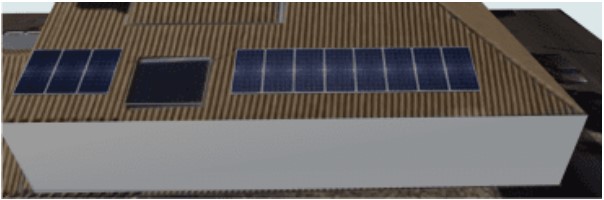
The image above illustrates a situation in which 11 modules must be connected in series, forming a string, however 3 modules will be far from the others. In this case there is a need to make an extension cable to connect one group to the other. If the connection scheme is of the type leapfrog (see in this article what it is leapfrog), you will need to make two extension cables.
In order for the size of the extension to be as small as possible, but enough to meet the need, and also because the projects (when they exist) are generally not sufficiently detailed, the crimping of the connectors usually happens after the cables have been passed during the assembly of the constructions. Precisely for this reason there is the possibility of crimping identical connectors at both ends, that is, male-male or female-female. This will cause the polarity of one of the sets to be inverted when the modules are connected.
In addition to reducing the energy generated, exposing the inverted module to reverse current is potentially dangerous and can cause fires. Fortunately, module inversion can be easily identified by measuring the open circuit voltage of the string after carrying out the assembly. In other words: this could be easily noticed if the professionals involved in photovoltaic assemblies at least knew what an open circuit voltage is and were instructed to measure it in the commissioning stage, which is the testing phase carried out after the assemblies have been carried out. . Often the need for commissioning has simply been neglected by professionals and installation companies.


System commissioning
A good photovoltaic project must go through the final commissioning phase, during which at least two things must be measured:
- VO.C. – Open circuit voltage of the string
- ISC – Short-circuit current of the string
See this article to understand the parameters of the IV curve of a module or string photovoltaic. Two of these parameters (VO.C. It is ISC) can easily be measured with a common, low-cost multimeter. Any photovoltaic system installer with minimal education should be able to perform these two basic tests.
For example, when considering a module with an open circuit voltage of 40 V, in a string with 11 modules in series it is estimated that the voltage VO.C. will be close to 440 V. Even with varying sunlight intensity, the output voltage of the modules undergoes little (practically no) change, which makes the open circuit voltage test result very reliable.
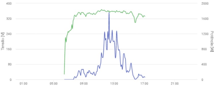
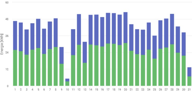
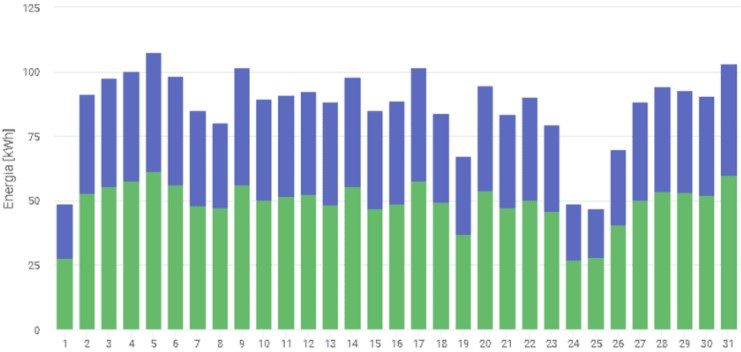
The figure below illustrates the result of measuring the voltage and power generated in a photovoltaic system already in operation. The green graph shows the operating voltage of a string photovoltaic, which remains constant for most of the day, suffering reductions or variations only at the beginning or very end of the day, when the intensity of solar radiation is very low. The best time to carry out commissioning tests for photovoltaic systems is always close to noon, when the open circuit voltage (or the operational voltage, which is shown in the graph below) remains approximately constant regardless of variations in the solar irradiance.
Divergent orientations in parallelism strings
When installing the system, problems related to data parallelism may also occur. strings with a different orientation or number of modules, which will negatively impact generation and increase the possibility of fire.
In reality, by rigorously analyzing these facts, this type of situation should be avoided during the design phase. Mix modules with different orientations and inclinations in the same string reveals the lack of preparation of many photovoltaic “designers” operating in the Brazilian market.
Regarding the parallel association of strings with different numbers of modules, this, in addition to a lack of preparation, reveals a great lack of responsibility. Any professional in the solar sector who is even minimally prepared knows that it is prohibited to parallel strings with different numbers of modules. What can happen if this rule is not followed? Look in this article the result of this “explosive” mixture of strings different connected to the same input of an inverter.
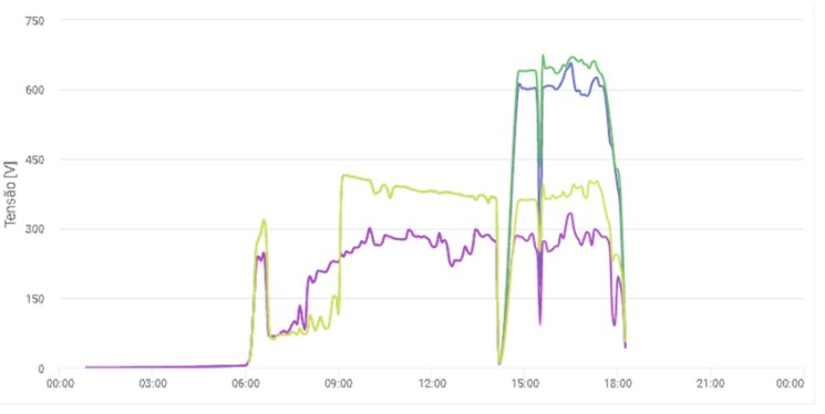
In Figure 5 we see the result of monitoring the voltage of a solar system with 4 strings of modules positioned in different orientations. The data presented was obtained on the day corrective maintenance was carried out on the system. From early in the morning until 2 pm there were two arrays (with 2 strings each). Each array (with 2 strings parallel) was connected to an inverter. To the strings This project had 11, 19, 9 and 18 modules. In short, the (totally absurd) situation was this:
- System with 2 inverters with 2 MPPT inputs on each. In total there were 4 MPPT inputs available. To the strings were grouped into arrays of 2. Each array was connected to just one input of an inverter. This situation is illustrated in Figure 6 below.
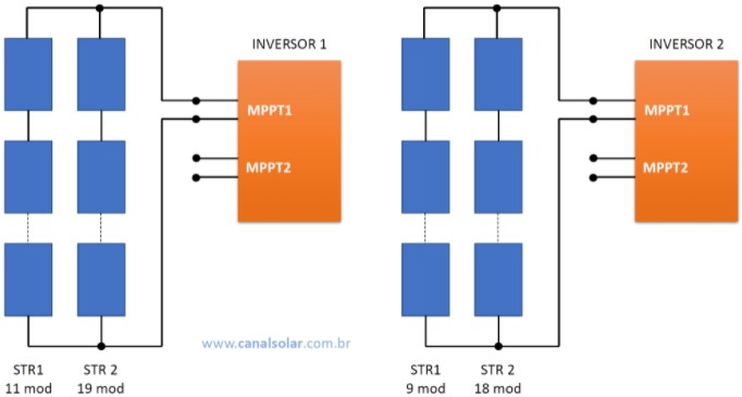
Let's look at the absurdity of the situation mentioned above. The inverters had 2 MPPT inputs each. It would therefore be possible to perfectly accommodate 4 strings different in this project. Due to the designer's (and also the installer's) lack of knowledge, this error went unnoticed during the design and installation phases. There certainly was no commissioning stage.
We observe in the graph in Figure 5 a green and a purple line, each corresponding to a group of 2 strings parallel. From 2pm the strings were separated and we noticed on the graph the record of 4 different voltages, now for each string individually. The tensions of strings individual values are much higher than the voltages obtained before 2 pm. This clearly shows that it is not a good idea to parallel strings of modules that operate under different conditions (tilt, orientation, shading or number of modules in series).
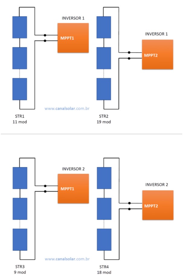
After corrective action, the system acquired this configuration:
- System with 2 inverters with 2 MPPT inputs on each. Each of the 4 strings was individually connected to one of the 4 available MPPT inputs. This situation is illustrated in Figure 7 below.
The result of the corrective action of a photovoltaic system, with the separation of strings that were previously in parallel, can be seen in the graphs in the following figures.
Contributors to this article:
Bruno Henrique Kikumoto de Paula – Electrical Engineer (UDESC), Masters in Electrical Engineering (UNICAMP). Specialist in project management, inspection and commissioning of photovoltaic systems. More than 10 years of experience in the photovoltaic industry. Instructor in solar energy courses at UNICAMP. See other articles by this author.
Marcelo Gradella Vilallva – Specialist in photovoltaic systems. Doctor (PhD), Master and Graduate in Electrical Engineering. Professor and researcher on the permanent staff at the Faculty of Electrical and Computer Engineering (FEEC) at UNICAMP – State University of Campinas. Director of LESF – Energy and Photovoltaic Systems Laboratory at UNICAMP. Author of more than 200 international technical articles in the areas of power electronics and photovoltaic systems. Author of the book “Photovoltaic Solar Energy – Concepts and Applications”. Pioneer in training in photovoltaic systems in Brazil. He is coordinator of the UNICAMP Solar Photovoltaic Energy Extension program (http://cursosolar.com.br), where he presents courses on Introduction to Photovoltaic Solar Energy, Design and Sizing of Systems with PVSyst and Installation and Integration of Systems Connected to the Electric Grid. See other articles by this author.
Become a Canal Solar partner. Contact us: [email protected]


2 Responses
Can we talk ? 21 98151 5555
Hi Geraldo, you can contact me via email [email protected]