
SMA recently launched a new line of products aimed at power generation in medium and large plants called Sunny Tripower Core2.
Within this line, the first inverter announced is the STP 110-60 model, with 110 kW of power and with multiple MPPTs.
The inverter, as it is a recent model, has a series of technologies and electrical parameters to modernize and become compatible with new energy generation demands.
In this article, we will analyze the product, explore what these technologies are and show their use cases.
Physical and electrical aspects
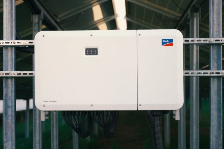
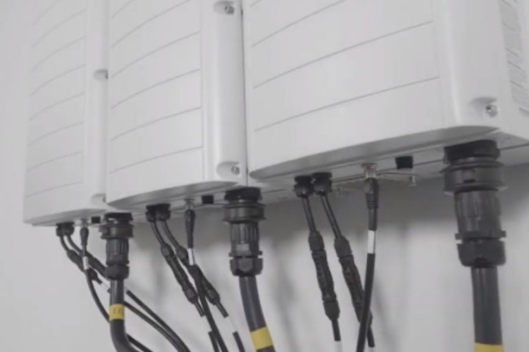
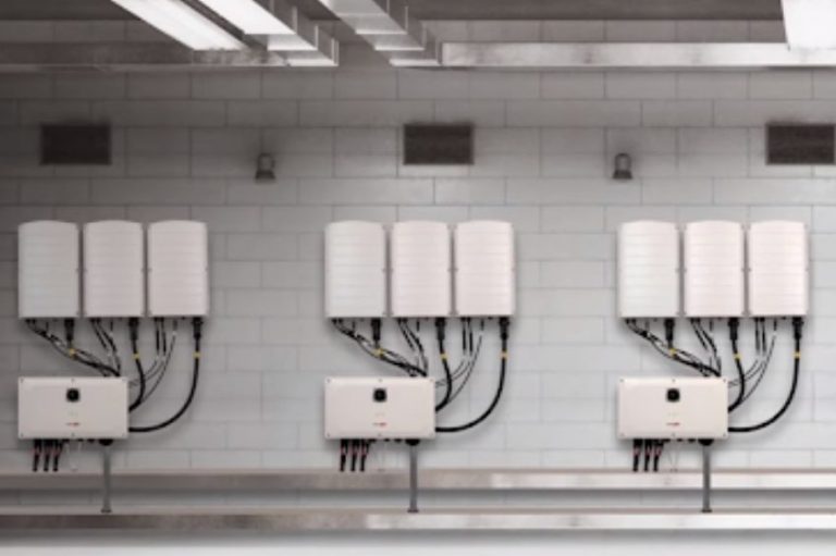
The inverter has a clean look, without screens and buttons, with a metallic finish and no exposed screws. Taking into account its power (110 kW) and the high number of connections and MPPTs (24 pairs of MC4 inputs distributed in 12 MPPTs), it remains very compact, measuring 1.12 m by 68 cm and only 36 cm in length. depth.
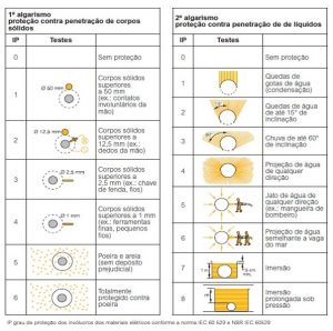
The construction of the equipment guarantees tightness and protection against the ingress of dust, with protection level IP 66 – according to Table 1.
Table 1: IP Rating
The equipment contains 4 DC disconnector switches, dividing the DC disconnection into blocks of 6 strings (3 MPPTs). In addition to the switches, the inverter also contains type 2 DPS on the DC side built into its protections.
Individual series protection by fuse is not mandatory for the suggested assembly of a string connected to each connection pair. As in this situation the number of strings in parallel per MPPT is 2, there is no risk of harmful reverse current in the modules.

As it has DC sectioning, does not require an individual fuse per series and contains type 2 SPDs at the inputs, the inverter does not require the use of a stringbox.
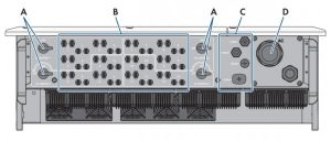
Figure 2: a) DC switches, b) 24 pairs of Sunclix connectors, c) passage points for connecting a monitoring system via cable, d) passage of AC cables.
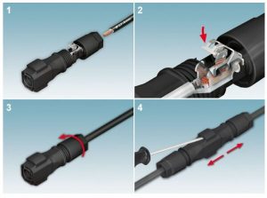
The connections available on the equipment use a standard known as Sunclix. Sunclix connectors differ from MC4 connections as they do not require the use of specific pliers to crimp the conductor, as the connection is made using a metal clip that can be opened and closed without having to re-terminate the cable.
Video 1: Assembly and disassembly process of Sunclix connectors
The inverter connects to the network via an Ethernet cable, and can use Modbus and SunSpec protocols to send data to SMA Data Manager intelligent monitoring units or a third-party SCADA system.
Regarding electrical parameters, we highlight a wide MPPT range and good current capacity per MPPT. It is interesting to note that the AC output, although it has a nominal voltage of 400V, can be configured to work with voltage between phases of 320 V to 460 V, a range in which it is easy to find compatible terminals, circuit breakers, transformers and SPDs on the market.
The inverter supports the connection of aluminum cables on the AC part, as long as they use a bimetallic terminal and anti-oxide paste.
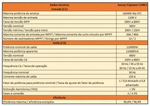
Table 2: Technical data found in the product data sheet
Technologies
Regarding technologies, the brand brings some highlights on the product page that can be important differentiators for your project. Are they:
- Use of Sunclix connectors: as shown previously, the Sunclix connector does not require special pliers to crimp the cable. The cable can also be removed from the connector without having to cut the crimped end;
- Capacity of up to 150% inverter scaling factor: being able to work with larger loads may make sense depending on the project. A larger load will not necessarily bring better LCOE, however, there are situations where the amount of energy required and the limitation of the AC network will lead the project to need a greater load. A loading limit of 150% also makes sense when thinking about bifacial systems, where the possible gains at the rear can make the effective loading greater than the loading when only taking into account the power data from the front of the panel;
- Compatible with DC voltage up to 1100 V: Many recent modules have Voc voltage above 50 V when corrected for minimum ambient temperature. An inverter with a 1100 V limit allows, for example, organizing a good part of the arrangements with 20 modules per series. An easier number to size tables and trackers than, for example, 18 or 19 modules in series;
- Compatible with bifacial modules: Inverters do not have the ability to “sense” that they are working with bifacial modules. The voltage and current reaching the inverter cannot be distinguished between front and rear. From the inverter sizing point of view, what changes when working with bifacial modules is that the current increases proportionally to the bifacial gain, that is, while most monofacial modules have currents of 9 to 11 A, bifacial modules easily reach 12 A to 15 A. An inverter being compatible with bifacial modules means that the maximum currents of the connectors and MPPTs take into account the possible higher currents;
- No need for stringbox: As discussed above, the inverter has all the mandatory DC protections, so the use of stringbox is not mandatory. The final decision whether or not to use a stringbox in this case is always up to the designer: there may be situations in which an external stringbox brings advantages to the system, even if the inverter has all the mandatory protections;
- Smart MPPT Shade Fix: In partial shading situations, where for example 3 modules of a string of 20 modules are fully shaded, the activation of the bypass diodes will cause deformations in the IV curve compared to situations without shading. These deformations can cause the inverter to choose an operating point IV that appears to be but is not the maximum. The technology ShadeFix causes the inverter to search for the point of maximum power over a wider range and always operate at the point of maximum global power, instead of the point of maximum apparent power.


One Response
The value of a String Box is very small in a system, it is not worth leaving it to the inverter. Inverters must be super protected to avoid interruptions. Imagine an internal DPS acting having to send the equipment for repair?? It's not worth it.