Before the growing photovoltaic panel installation market in Brazil, the technical responsibility involved in this type of service must be widely discussed and encouraged.
The technical areas that make up this process are, in some cases, neglected and undervalued in a market that presents low-cost options and questionable technical quality. When the technical areas of this process are mentioned, it is natural to remember Electrical Engineering.
However, it works together, among others, on Occupational Safety, Environmental Impact Studies (in large projects), Load Lifting and Handling activities and Structural Engineering. The latter is the discussion objective of this article.
Structural engineering is responsible for evaluating and certifying that a given structure is capable of receiving the installation of the plates. It is evaluated from the original design dimension to the actual integrity conditions of the structure, proposed reinforcements and changes that promote safety during and after the installation stage. This ensures compliance with current regulatory criteria.
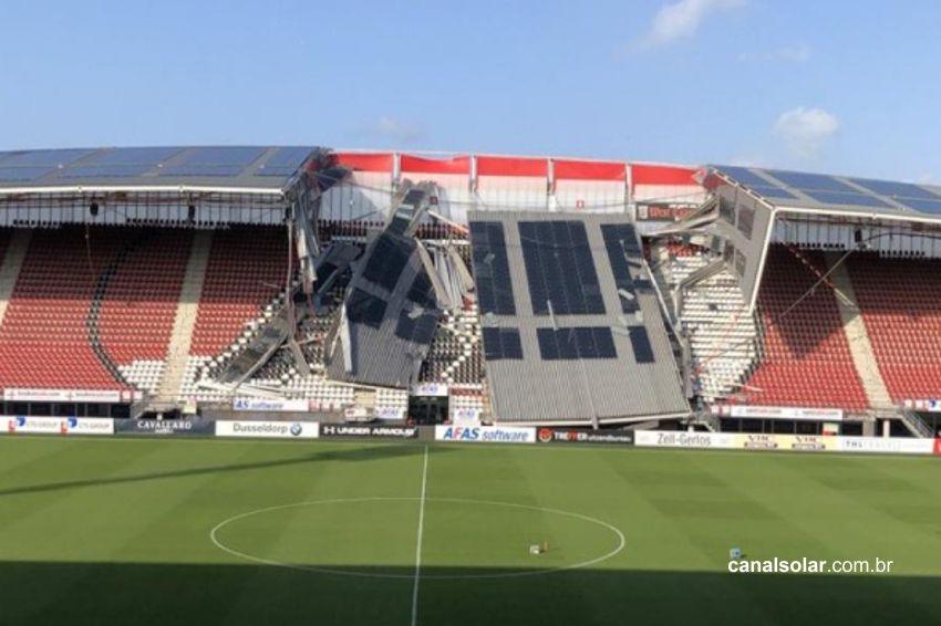
On your indicator Roof meter, Canal Solar records the statistics of harmful results, possibly due to neglect of structural assessment on roofs on which photovoltaic panels were installed.

The panels represent an increase in load in an order of magnitude similar to the total weight of the metallic structure itself, which was not originally designed for this load. This article presents a technical review on the structural design of roofs specifically due to the installation of photovoltaic panels.
The interpretations of standards and practical recommendations are based on the experience of HRD Soluções de Engenharia’s technical staff. The objective is to discuss and present applicable technical references and a case study on the relevance of Structural Engineering in the solar energy generation sector in Brazil.
Literature review
The structural calculation of roofs and their support components must be based on minimum loads and stiffness and resistance criteria established by current Brazilian standards. Table 1 presents the main Brazilian standards for structural design.
Table 1: Main Brazilian standards for structural design

Regarding sizing criteria, international references can be used such as:
- For cold-formed profiles: AISI – Cold-Formed Steel Design Manual (AISI S100) and Eurocode 3;
- For rolled or welded profiles: AISC-360-16: Specification for Structural Steel Buildings and Eurocode 3;
- For concrete structures: Eurocode 2 and ACI-318;
- For actions and combinations: ASCE-07 and Eurocode 1.
Minimum shares
The structural design of roof elements and sheds subjected to the installation of solar panels must be carried out following the action assumptions established in the standards NBR 6120 It is NBR 6123.
NBR 6120
In September 2019, an extensive review of this standard was issued by ABNT. More rigorous details and specifications for permanent actions and variable actions have been included.
Permanent actions
The values presented in this section are minimum nominal indications in the absence of more rigorous experimentation. In relation to the application of roofs and installation of photovoltaic panels, Table 5 (Figure 2) stands out with indications of weights for different types of tiles, already considering the superposition, fixing elements and water absorption of the components, and the table 8 (Figure 3) for ceilings, ducts and sprinklers. For photovoltaic panels, a load of 0.15 kN/m² is recommended, which already takes into account the weight of the fixings.


Variable actions
General indications for variable loads on roofs are presented in item 6.4 of NBR 6120. For reinforced concrete structures, mixed steel and concrete and structural masonry, in case of defined use or possibility of use, the values in Table 10 of NBR 6120 (1) (Figure 4). In the specific case of solar or photovoltaic heating plates, the application of 1.5 kN/m² is recommended.

For roofs made up of metallic structures, the revision of NBR 6120 establishes that the overload can vary from 0.25 to 0.50 kN/m², depending on the slope of the roof (Figure 6). In cases of slopes greater than 1% and less than 3%, it is permitted to adopt the value of 0.25 kN/m² as long as the stiffness criteria indicated in Annex D of NBR 6120 are met.
Furthermore, the requirement for resistance to a point load in the most unfavorable position of 1 kN was maintained for purlins and shears. It should be noted that the new version of NBR 6120 indicates that this value does not include the weight of installations in general, unlike the permitted limit of 0.05 kN/m² in the current version of the NBR 6120. NBR 8800.
It is therefore recommended that the premises of this new review be followed and the weight of all equipment supported on the roof be considered in its sizing. Figure 5 highlights this section of the standard, highlighting the mention of photovoltaic panels.


It is important to highlight that the values indicated in Figure 6 are minimum recommendations. In specific cases, with probability of material accumulation (mining, steel, cement industries, etc.), higher values must be adopted considering factors such as angle of internal friction and of the material with the surface, specific weight and inclination of the roof.

NBR 6123
Actions due to wind must be adopted in accordance with the premises of NBR6123. For roofs of rectangular buildings, the aerodynamic coefficients indicated in item 6 of the standard must be adopted. These coefficients vary depending on the angle of the roof and its configuration (amount of water, multiple roofs and their shapes) and the ratio between free space and height.

Depending on the internal pressure and the structural configuration of the roof, pressure or suction loads may occur on the shears. Figure 7 presents a qualitative example of force distribution in constructions with two opposite sides that are equally permeable and others that are impermeable.
Structural sizing
Loading combinations must be established as per NBR 8681. The specific standards for steel structures, concrete or cold-formed profiles also present the indicated increase factors.
The limit states, detailed in the following items, indicate the reference values above which a structure does not perform adequately according to its specification/project. These limits may involve, for example, excessive flexibility, vibration, nucleation and propagation of cracks, or even the rupture of a component.
Ultimate limit state
The structural elements of the roof, their fixing elements and support columns must be designed for all applicable ultimate limit states indicated in their specific standards.
As described in NBR 8800, these states are related to the safety of the structure subject to the most unfavorable combinations of actions foreseen throughout its useful life, during construction or when a special or exceptional action takes place. Figure 8 shows the latest normal combinations indicated by NBR8800.

Permanent actions can be grouped at the designer's discretion and, for type 2 buildings (whose variable loads do not exceed 5 kN/m², applicable to roofs), 1.40, 1.30 or 1.20 can be used for normal combinations, special or construction and exceptional respectively.
In cases where the permanent action is favorable to the verified limit state, the value of 1.00 must be adopted (Example: Case of wind suction on the roof). Variable actions are combined as long as their effect is unfavorable to the safety of the structure. Just like permanent variables, variables can be grouped or evaluated separately.
service limit state
Service limit states are related to the performance of the structure under normal conditions of use. As described in reference (6), the occurrence of this limit state can harm the appearance and functionality of a building. In the case of roofs, excessive accumulation of water and visual discomfort due to excessive sagging may occur.
As indicated in NBR 8800, the displacement limits established in Table 2 are recommended for scissors and purlins. Furthermore, for roofs with a slope lower than 3%, the stiffness criteria must be met to avoid progressive pooling on roofs in accordance with Annex D of NBR 6120.
Table 2: Recommended maximum displacements

Stability
The stability of pillars that support roofs is something that must be taken into account during the structural assessment due to the addition of panels. Of particular note are the verification of stiffness and resistance of elements that impose restrictions on these columns and the reevaluation of imperfections that depend on the values of gravitational loads.
The initial geometric imperfections can be evaluated with the inclusion of notional horizontal forces (0.3% of gravitational loads), applied separately in each direction of the column. NBR 8800 indicates that it is not necessary to combine this force with other horizontal actions, such as wind.
The non-linearity effect of the material, in turn, can be simplified by reducing the stiffness to 80% from the nominal value. In general, second-order structural analysis can be carried out by any method that considers the effects of geometric and material nonlinearity.
Warning points: Structural damage
The state of integrity of the structure prior to the installation of solar panels must be inspected. Excessive deformations, modifications and cutout in structural elements must be documented and renovation/reinforcement solutions must be proposed.
Figure 9 shows a shear with evidence of buckling on one diagonal, probably caused during roof overload. As shown in Figure 10, it is common to find damage caused by vehicle impacts on columns in logistics warehouses. These non-conformities must be adequately corrected.


Warning points: Connections
The profile splicing regions and scissor supports must be reevaluated. The state of conservation, integrity and execution must be carefully inspected. Inadequate welding, corroded or untorqued screws, misalignment of connection plates, etc., can represent points of weakness and risk of collapse of these covers.
Evidently, if they are in an adequate state of integrity, manufacturing and assembly, these elements must be capable of withstanding the increased stress due to the load of the photovoltaic panels.

Authors
Engineers Diego Correia Martins and Hugo Gatti Ladeia Costa – HRD Engineering Solutions [email protected]/[email protected]


