
Photovoltaic inverters are designed to convert all the power that can be made available by photovoltaic modules, seeking the maximum power of the photovoltaic array through a maximum power point tracking algorithm (MPPT – maximum power point tracking).
However, when the internal temperature of the inverter exceeds its nominal specification, a protection control is activated that moves the operating point to a region below the maximum power point [1].
In other words, the inverter reduces its output power when it reaches certain temperatures. This process is known as thermal 'derating' of power. The power of the photovoltaic inverter resumes when the equipment reaches safe operating temperatures.
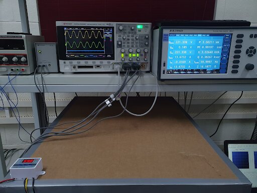
In this article, temperature curves of commercial inverters obtained experimentally will be shown, through tests carried out at the LESF (Energy and Photovoltaic Systems Laboratory) at UNICAMP.
You may be wondering: why is it important for the inverter to reduce power by temperature? To answer the question, first let's talk about how temperature can influence the operation of the inverter.
The literature has presented several articles in which the inverter has been identified as the equipment in the photovoltaic system that presents the highest number of failures. In addition to these failures generating maintenance costs, there is also the aggravating factor of downtime when the system does not generate energy.
These failures are explained by the large number of internal components of the inverter, including power semiconductors and capacitors, which have their useful life reduced when working at high temperatures for prolonged periods, which increases the probability of equipment failure.
These failures generally occur in capacitors and transistors of the IGBT and MOSFET types, which are the most sensitive and failure-prone components of the photovoltaic inverter [2]. High power transistors generate heat while in operating condition, but these components have low heat dissipation capacity [3].
Therefore, to solve this problem, some equipment on the market opt for active heatsinks with fans, also known as forced dissipation. It is important to mention the other type of dissipation that exists: natural dissipation, that is, without a fan or fan.
Inverters with forced dissipation tend not to reach high temperatures (in their housing or thermal fins) as easily. On the other hand, in inverters with natural dissipation, slower thermal dynamics are expected, with a higher final temperature.
Below are practical results of two photovoltaic inverters with different dissipation strategies and in the same category, that is, single-phase and with nominal power in the range of a few kilowatts. The characteristics of the inverters are summarized in Table 1.
Table 1: Characteristics of the evaluated photovoltaic inverters
|
Equipment |
Dissipation |
Power (kW) |
|
Inverter A |
Forced Dissipation |
2 |
|
Inverter B |
Natural Dissipation |
5 |
The temperature was measured at an external point on the heat sink of each equipment and the ambient temperature was maintained close to 25 °C during the experiments. In Figure 1, inverter A had its temperature limited to 45°C, as the fan was activated at around 38°C.
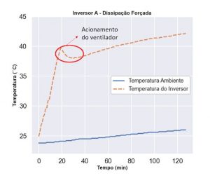
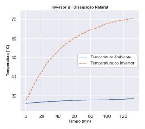
Figure 2 shows the thermal behavior of inverter B during the experiment. In this case, the heatsink temperature exceeded 70°C, as this equipment has natural dissipation and does not use fans.
In the previous graphs we show the evolution of the heat sink temperature over time, with the inverters operating at their maximum load, that is, with their inputs receiving a photovoltaic array with peak power compatible with the nominal power of the inverter – while the temperature environment was controlled at around 25°C.
Thermal derating curves
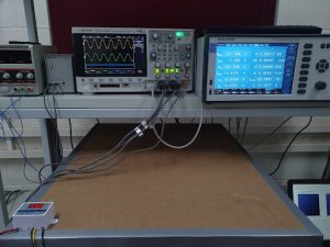
In a new experiment, we varied the ambient temperature during the operation of an inverter by placing it inside a temperature-controlled thermal oven.
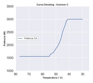
Figure 3 presents graphs of power by temperature (ambient) obtained from a new experiment whose objective was to trace the inverter's derating curve by temperature and compare it with the behavior reported in the equipment's data sheet.
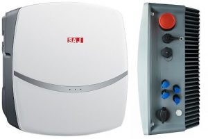
This test was carried out with a 3 kW SAJ R5 inverter with natural dissipation. The equipment specifications mention that it can reduce the output power (AC power) from 45°C and the maximum supported ambient temperature is 60°C.
The experiment was carried out with a thermal chamber, with controlled temperature, and was divided into stages with the aim of searching for the experimental temperature value at which the power reduction begins to occur.
- Stage 1 (E1): thermal chamber programmed up to 45°C. If there was no power reduction at this temperature, the thermal chamber would go to Stage 2;
- Stage 2 (E2): thermal chamber programmed to vary the ambient temperature from 46°C to 60°C. In the same way as in Stage 1, if there was no derating, the experiment would go to Stage 3.
- Stage 3 (E3): thermal chamber programmed at 61°C ≤ 70°C. If there was no reduction, proceed to Stage 4;
Stage 4 (E4): thermal chamber programmed at 71°C ≤ 80°C. If there was no reduction, the experiment would advance to the next stages.
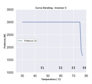
As shown in Figure 3, the tested photovoltaic inverter showed power reduction from 74°C (ambient) and the maximum temperature tested was 77°C.
Figure 4 shows the behavior of the inverter during cooling from room temperature. It is possible to check the AC power increasing from 65°C and stabilizing at the nominal power when reaching close to 40°C, a value slightly below the initial derating temperature specified in the data sheet.
Conclusion
In this article, experimental results on the thermal behavior of photovoltaic inverters were presented. At the beginning of the article we show temperature graphs over time, which illustrate different behaviors according to the cooling method used in each piece of equipment.
Equipment with two types of thermal dissipation systems was analyzed: completely natural and with forced ventilation.
Working under the same conditions (with nominal power and controlled ambient temperature), the inverter with natural dissipation reached a temperature above 70°C (measured in the external area of the heatsink) and presented slower thermal dynamics. The inverter with forced ventilation, on the other hand, showed that it is capable of controlling the temperature more quickly and kept its heatsink at a temperature below 45°C.
An interesting result of this work was the experimental verification of the thermal derating behavior (power reduction with temperature) of a 3 kW grid-tie inverter with natural ventilation.
The graph in Figure 3 shows the result of a test with a sudden increase in temperature, an atypical situation in normal operating conditions. In this case we found that the derating mechanism started to act when the ambient temperature reached 74°C, causing the output power to quickly decrease from 3 kW (nominal) to close to 1.5 kW.
Then, as shown in Figure 4, the room temperature was gradually reduced. The power increased from 1.5 kW and the equipment had its nominal output power (3 kW) restored from a temperature value slightly below 45°C, as expected from the manufacturer's data sheet.
The ability of this equipment to automatically regulate its output power was then proven with the aim of preserving its internal components, avoiding damage due to overheating, especially in the power electronic transistors.
It is important to mention that inverters are not fail-safe equipment and require maintenance, given their complexity and high number of electronic components, which include transistors and capacitors – which are the most sensitive components.
The power thermal derating mechanism is important for protecting the inverter and increasing its useful life when subjected to aggressive operating conditions, especially in relation to ambient temperature.
References
[1] AL Perin, “Analysis of the influence of different cooling strategies on the performance and durability of grid-connected photovoltaic system inverters,” 2016.
[2] M. Shahzad, K. VS Bharath., M.A. Khan and A. Haque, “Review on Reliability of Power Electronic Components in Photovoltaic Inverters”, 2019 International Conference on Power Electronics, Control and Automation (ICPECA), 2019, pp . 1- 6, doi: 10.1109 / ICPECA47973.2019.8975585.
[3] P. Hacke, S. Lokanath, P. Williams, A. Vasan, P. Sochor, G. TamizhMani, H. Shinohara, and S. Kurtz, “A status review of photovoltaic power conversion equipment reliability, safety, and quality assurance protocols,” Renewable and Sustainable Energy Reviews, vol. 82, pp. 1097–1112, 2018. [Online]. Available: https://www.sciencedirect.com/science/article/pii/S1364032117311103


One Response
Great article, congratulations Geyciane Pinheiro. For customers who have a central inverter, I recommend that they install a forced ventilation system, which I use in my inverter.
In my inverter the internal temperature (according to the monitoring system) does not exceed 29 degrees and in the heatsinks it does not reach 35 degrees. My intention is to increase the useful life of the internal components. I know I won't avoid maintenance, however, if I can postpone it it will be a saving. The automatic ventilation system consists of an electronic controller with thermocouple, fan and power source.