
The standard for commissioning photovoltaic systems ABNT NBR 16274 provides that any photovoltaic system must go through the testing and commissioning documentation stage.
The standard provides a kind of step-by-step process, which fits well into a traditional project with modules, DC string cabling and inverter.
However, some design topologies such as systems with optimizers and microinverters have particularities in their construction and operation, which makes adaptations necessary in measurements to verify the system's functioning.
This article will address the main steps and differences in commissioning a plant with a traditional topology and one with optimizers.
We have discussed it previously here on Solar Channel what is the commissioning of a plant and what equipment we usually use for it, but without taking into account the peculiarities of systems with optimizers.
Briefly, the tests provided for in the commissioning standard are:
- Project inspection;
- Visual inspection of the installation;
- Grounding continuity test;
- String tension test: measurement of Voc voltage and operating voltage);
- String current test: measurement of current Isc and operating current;
- String-box tests: checking voltages according to system assembly;
- Insulation resistance test: between positive and ground, negative and ground and short circuit of positive and negative with ground.
Design inspection and visual inspection
At this stage, the project is analyzed in search of design errors and equipment incompatibility. A project with incorrect assumptions or equipment outside the limits of functionality and incorrectly selected electrical quantities generally does not perform well.
There is no big difference here between the commissioning of a traditional system and that of a system with optimizers, all that is needed is special care to check the compatibility of the optimizers with the modules and inverter.
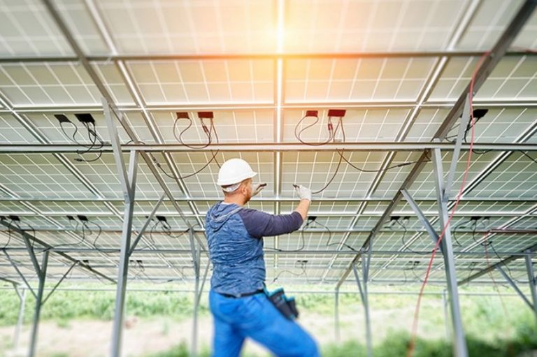
The first field analysis to be carried out is visual inspection. The installation of the system may end up not following what was designed on paper, either due to carelessness on the part of the installer or due to the need to adapt to a problem perceived in the field that was not foreseen in the design.
At this stage it is necessary to visually check the installation of the modules, the integrity of the connections and cables, the installation of the optimizer and inverter and the organization of the string-box.
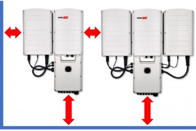
Due to the generation and dissipation of heat by the optimizer and the inverter, it is important to check whether the minimum distances recommended in the manual are being followed.
Failure to comply with this item may cause excessive heating, damaging the system's generation, as already discussed in the article Photovoltaic inverter power reduction due to temperature.
Commissioning tests
Current and voltage measurements
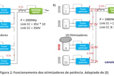
Before discussing measured quantities, we need to understand how a system composed of optimizers works electrically. There is more than one type of topology with optimizers on the market. In this article we will cover the most common topology, which is SolarEdge systems.
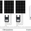
The optimizers work by conditioning the direct current energy of 1 or 2 modules at other levels of direct current and voltage, and can later be connected in series and parallel to the specific inverter for this application.
One of the differences between the optimizers studied is the SafeDC safety function, which reduces voltage levels in the DC circuits to 1V per optimizer when it detects that the inverter is off.
In other words, imagining an optimizer disconnected from the inverter but connected to a module, we would be able to measure a value close to the module's Voc at the optimizer input but only 1V of voltage at the optimizer's output terminals.
Due to this effect, when we measure the voltage Voc of the string to check if the assembly is correct in relation to the number of optimizers, we should expect to have 1V for each optimizer connected in series.
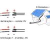
Another problem that we want to protect ourselves from is the wrong termination of extension cables, which can result in a mix of positive and negative terminals and therefore a connection with reversed polarity.
Array voltage measurement brings a quick answer to this problem. At all points where we have parallelism, we will need to measure the polarity of the parallelized circuits so that there is no inverted assembly.
If there is a polarity change between negative and positive in one of the series (strings), the optimizer will not be able to communicate with the inverter and will remain in 1V safety mode.
Due to the SafeDC safety feature, we will not be able to measure any current when short-circuiting the optimizer outputs.
The short-circuit current test in systems with optimizers can be carried out individually on the modules, which is laborious and can be indirectly verified later when monitoring the optimizer, since a module with Isc current far outside its specification will certainly have deficiency in energy generation. Therefore, the short-circuit current test is not performed on these systems.

Operating voltage and current tests in traditional systems are useful to check whether there are serious assembly flaws or whether there is any other problem in the arrangement that causes generation to become very low.
As in systems with optimizers we have individualized monitoring of the modules and there is communication between them and the inverter, it is very simple to find the defective item, in addition to the fact that any mistaken connection between the optimizers will cause them to indicate a communication or operation failure. and the inverter does not turn on.
Inverters suitable for using these optimizers usually work with a fixed voltage level at the input. Each optimizer, in turn, works with a certain output voltage such that the power extracted is maximum for each module.
An operating voltage test carried out between the positive and negative poles of an arrangement with optimizers must measure voltage levels close to this fixed voltage, which can be found in the inverter manual.
Insulation resistance measurement
Insulation resistance measurement must be carried out to check whether there is a damaged conductor or connector causing an earth leakage. To make this measurement we need special equipment, the megometer, which is capable of measuring resistances in the order of hundreds of megohms.
You must disconnect the positive and negative cables from the optimizer array and the inverter and measure the insulation resistance that occurs between each of these cables and the grounding point. This method is referred to in the standard as insulation test method 1.
The standard requires an insulation resistance of at least 1 MOhm. The manufacturer recommends that this resistance be at least 200 MOhm.
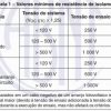
We can also perform the type 2 insulation test, which checks the insulation between the positive and negative short circuits with ground. As the conductors will be short-circuited, there must be a device capable of interrupting the current in the circuit to prevent the formation of an electric arc when disconnecting it. The values recommended by the manufacturer vary depending on the product and are shown in the following figures.
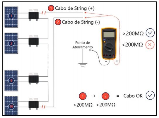
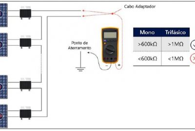
Table taken from the NBR 16274 standard relating system voltages, test voltages and minimum insulation resistance when commissioning photovoltaic systems:
Continuity of equipotentialization
The equipotentialization and grounding of the system must be continuous. To do this, it is necessary to carry out a continuity test between each of the interfaces of these connections.
In other words, we need to check the continuity of the grounding between the modules and the structures, between the modules and the optimizers, between the optimizers and the string-box and the inverter, between the metallic housing of the inverter and the earth conductor and between the connection of the inverter with the general grounding of the installation.
IV curve analysis
As the optimizers do not turn on without the presence of a compatible inverter, and as the inverters and optimizers seek to work with a fixed voltage, we were unable to test the array's IV curve tracer.
In traditional systems, we can connect a string to the tracer and analyze its current and voltage response and detect defects in modules, for example.
In systems with optimizers, the health status of the modules will be checked through individual monitoring during system operation. Therefore, the IV curve tracer test is unnecessary and not applicable in photovoltaic systems with optimizers.
Thermographic analysis
Thermographic analysis is very useful for detecting poor connections. In systems with optimizers there is no difference in application. The thermal camera must be used to analyze the modules (to look for damaged cells, for example) and at the system connection points.
Inverter configuration and app
The final step of commissioning must be the configuration of the inverter and its connection to the grid. Each brand and each model has its specific process – therefore, the installer must pay attention to the procedure described in the manual.
Once the configuration is complete, the installer will be able to check problems for signs of error, if any other defect has been tested, and also carry out monitoring, which is extremely important to analyze the plant's performance at the beginning of its operation and also throughout of its useful life.
Documentation and monitoring
All stages of the test must be documented and preferably photographed. This documentation must form a report in accordance with the format shown in Annexes A and B of the NBR 16274 standard.
Monitoring the plant's performance is also essential, as through this we can detect problems in generation that may have escaped the plant commissioning stage.
Here, systems with optimizers have a significant advantage: individualized monitoring per optimizer. This way, problems located in specific modules can be quickly identified, making maintenance work more agile.
Learn more
Also check out these articles from Solar Channel that address the commissioning of photovoltaic systems:


3 Responses
Very good article, congratulations!
Excellent breakdown of the content Matthew. Congratulations.
Very interesting material for improving engineering and developing activities.