
A solar plant project can be divided into three parts:
- Generation system: composed of boards, inverters, low voltage distribution circuits in direct and alternating current;
- Grounding system: promotes personnel and equipment safety throughout the facility and;
- Medium voltage system: consisting of the medium voltage cabin, transformation and distribution circuits.
The primary medium voltage cabin is the part of the project that will integrate the generation installation with the concessionaire's distribution system.
For its design, it is important to observe Brazilian standards NBR 14039 – Medium Voltage Installations, NBR 5419 – Protection against atmospheric discharges, NBR 5410 – Low Voltage Installations, among others.
In addition, comply with the respective technical standards for energy supply from the concessionaires. This is because each dealership has its own systemic characteristics that must be met for safe and reliable operation.
Medium voltage cabin
The sizing of the medium voltage cabin or primary cabin must consider the generation and load capacity of the enterprise and observe the characteristics of the distribution system to which it will be connected.
Therefore, the configuration of the cabin will depend on the design of the plant project, in which generation capacity is a relevant factor. Better explained, a cabin is made up of three sectors:
- Billing measurement;
- Protection and;
- Transformation.
Depending on the capacity of the plant, these three sectors can be housed in the same environment. For plants with a capacity above 1 MW, the transformation sector is usually used separately from the measurement and protection sectors.
In this case, the coupling transformers, which interface the plant with the utility network, are located close to the inverters. Hence the need to build a medium voltage circuit (network), interconnecting the protection sector with the transformation sector. Figure 1 shows these configurations.
The)  B)
B)
 and separated from the measuring cabin, close to the inverters (b)")
If, on the one hand, the transformation sector may be distant from other sectors, it is important to know that in both configurations, the measurement and protection sectors must be close. Therefore, a medium voltage cabinet can be designed with three or two sectors. The primary cabin can be sheltered or outdoors, as shown in Figures 2 and 3.


There are also simplified transformer stations (Figure 4), in which the transformer is installed on a pole. In this case, billing measurement and low voltage protection are housed in a specific cabin.

In the case of minigeneration, most utilities require that the cabin be sheltered, which can be made of masonry or even armored. It is true that masonry cabins have a lower cost than armored ones, but many manufacturers are already approved by dealerships, meeting their technical requirements. It is therefore appropriate to make an economic assessment of which installation is best.
Measurement Sector
The measurement sector (Figure 5) is the area where the concessionaire will install its measurement equipment. In this sector, the cabin design must allow the installation of current and potential transformers, the famous CTs and TPs, which will be used to measure billing. The project must meet the dimensional, security and access aspects requested by the concessionaire.

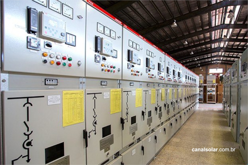
Protection Sector
This sector is responsible for protecting the plant, mainly in the protection zone between the connection point with the distributor and the primary terminals of the coupling transformers (Figure 1). The main components of this sector are: medium voltage circuit breaker, protection relay, current and potential transformers. The cubicle must be sized to receive this equipment and comply with the requirements of each dealership.
The circuit breaker is the equipment responsible for the intentional or unintentional disconnection of the plant's connection with the concessionaire's distribution system. Therefore, it must be capable of interrupting load and short-circuit currents, not only from the plant's internal installation, but also from the utility's network. It is equipment that can be maneuvered manually or automatically.
Protection relays
The circuit breaker by itself does not interrupt a short circuit or even a load current. Human action or a relay is required for it to act. The automatic operation of the circuit breaker depends on the relay. The relay is a piece of equipment that combines several functionalities and sends opening and closing commands to the circuit breaker.
The opening or closing of the circuit breaker controlled by the relay will depend on its programming or, as is better known, its parameterization. So, we have the relay that will execute the circuit breaker automation, but how is this anomaly detection in the system carried out? The relay is the device that will perceive and measure system events and check whether they are within certain electrical parameters.
The relay receives signals from the medium voltage system from sensors connected to it, such as current and potential transformers (Figure 6). These sensors must be appropriately sized depending on the nominal characteristics and short circuit levels present in the system to which they are connected.

The)
 Relays; b) TCs and c) TPs")
Protection study
Anomalies in the electrical system usually occur in the form of short circuits, overvoltage, undervoltage, frequency variation, among others. When a photovoltaic generator is inserted into the utility's network, the network's short circuit level increases, as there is now the contribution of a current coming from the generator.

This contributes to the increase in the level of short circuits throughout the electrical system. It is up to the designer to evaluate this elevation so that all system components are suitable to support it. Utilities, for example, require a certain short circuit value that cannot be exceeded.
In the protection study, the designer must evaluate the short circuit contributions that will cause the activation of your cabin's protections. If the short circuit is inside the plant's facilities, the current contribution that will pass through the cabin is that of the concessionaire (Isist – Figure 7).

If the short circuit is in the concessionaire's distribution network, the contribution to the short circuit will be from the generation itself (Iger – Figure 8).

When the short circuit is internal to the plant, the designer must guarantee selectivity between the utility and plant protections. In other words, the protective equipment closest to the short circuit must act first. Taking Figure 8 as a reference, it is desired that for internal defects in the plant, the “D plant” circuit breaker acts before the “D distr” circuit breaker (rear protection) so that there is selectivity between these protective equipment.
This analysis is interactive and requires several attempts until the protection requirements are met, such as pick-up adjustments, timing with a certain time difference between the protections involved, transformer magnetization current, etc.
Selectivity
Selectivity is the ability of the protective equipment closest to the fault to always anticipate the action of the rear equipment, regardless of whether the fault is transient or permanent.
Figure 9 illustrates this concept well: if a fault occurs at Point 1, Recloser R1 must act before Circuit Breaker D1 to guarantee selectivity between these two protective equipment. As for the fault at Point 2, it is desired that Circuit Breaker D2 acts before Recloser R1.

Therefore, for faults inside the plant, the protection engineer must make adjustments to the medium voltage cabin protections to ensure that selectivity occurs with the back-up (utility) protections for faults internal to the plant. This analysis is interactive and requires several attempts until the protection requirements are met, such as pick-up adjustments, timing with a certain time difference between the protections involved, transformer magnetization current, etc.

Selectivity can be visualized and studied by constructing a graph on a logarithmic scale of Time x Current. This graph is known as a coordinate chart and must contain the utility and plant protection curves, as seen in Figure 9. In the coordinate chart shown, the blue curve represents the utility's protection adjustments, while the red curves represent the utility's protection adjustments. power plant. Typically, 4 types of curves are used:
- NI (Inverse Normal);
- MI (Very Inverse);
- EI (Extremely Inverse);
- TD (Constant Time or Definite Time).
These curves are standardized by IEC and IEEE standards and can be chosen at the discretion of the protection engineer to meet protection requirements. Current relays not only allow you to choose any of these curves, but also allow you to design your own. The adjustments proposed in the protection study and coordination charts will be evaluated by the concessionaire. Through the coordination charts, the concessionaire will verify whether the proposed adjustments are selective with its protections.
Medium Voltage Circuit
If the plant is designed to have the transformation sector far from the connection point with the concessionaire, there will be a need to build a medium voltage distribution network. This network can be aerial or even underground (Figure 11), the latter being the most commonly used in photovoltaic plants.

In the design of an underground network, current conduction capacity correction factors defined in standards must be considered, such as soil temperature, soil thermal resistivity and grouping to choose the conductor that allows all the energy produced by the plant to flow. . The medium voltage network must also be protected by the primary cabin protections against overload and short circuit.
Transformation Sector
When designing the transformation sector project, it is important to decide which type of transformer will be used, oil or dry. Although the oil-filled transformer has a lower cost than the oil-insulated transformer, the cost of adapting the infrastructure must be considered in the project.

According to standard NBR 14039 and utility supply standards, the oil transformer installation location must provide a containment box in the event of an oil leak, as shown in figure 11.
")
The transformer's function is to enable the connection of the concessionaire's distribution system with the plant's generation. This is why it is known as coupling transformer. In its specification, the nominal voltage of the concessionaire's distribution system must be considered, as well as the nominal operating voltage of the inverters that will be connected to it.
Transformers are built with taps on the primary windings, called taps. For example, in an 11.9 kV system, the plant can be installed in a location where the supply voltage is 11.4 kV. For the secondary voltage to be as close to 1 pu, it is interesting that the transformer has a primary tap of 11.4 kV.
Utilities indicate the taps that a transformer must have depending on the nominal voltage of the distribution system. Furthermore, the designer can specify other taps, as necessary. Another important factor to be evaluated when specifying the transformer is the presence of harmonic components caused by the inverters, that is, the calculation of the K factor.
This factor indicates the losses that a given transformer will have due to harmonics generated by non-linear loads. Unitary K factor is the conventional transformer and K factor greater than 1 indicates that the transformer must have a design that supports losses resulting from the harmonics present.
Therefore, it is important that, when purchasing the transformer, the report of harmonic components caused by the inverters is presented to the manufacturer. Transformer protection can be provided by the primary cabinet itself, the input circuit breaker at the connection point or it can even be protected in the area where it is installed. This will depend on the installation’s protection analysis.
If protection is adopted next to the transformer, the relay does not need to have the same functions as the medium voltage cabin, and can be a relay with fewer functions. Another possibility is to use differential protection, but this is less applied in most installations for transformers smaller than 5 MVA.
Primary cabin course
The items mentioned above are presented in more detail in the primary cabin course promoted by Canal Solar, where the designer will receive guidance on:
- Size the main equipment of a primary cabin;
- Size the medium voltage network;
- Roadmap for preparing a protection study;
- Construction of coordination charts, with application to be made available;
- Prepare short circuit calculation using an application.


