
Reverse current is an unwanted and dangerous effect that can occur in a string of photovoltaic panels. Reverse current is the flow of current in the opposite direction to the normal operating current flow of a photovoltaic module.
This phenomenon can occur in sets of modules with strings in parallel when the open circuit voltage (Voc) of one string is lower than the open circuit voltage of the other strings.
When this occurs, the affected string behaves analogously to a system load, dissipating the heat generated by this reverse current passage.
In a photovoltaic generator properly sized and operating without defects, there is no significant reverse current.
Total or partial shading of modules does not have a significant influence on the occurrence of reverse current in micro and mini generation systems, since the effect that shading causes on the module's open circuit voltage is not significant [1] when there is a small amount of parallel strings. For this reason, reverse current is not a phenomenon that easily occurs during normal operation (without failures or defects) in most systems.
On the other hand, in large generating plants, with a large number of parallel strings, reverse current can occur due to differences in open-circuit voltage caused by shadows [2], by inequalities between modules or by defects (such as short circuit of some cell or some module of the string).

In cases of defects in the photovoltaic generator (e.g. short circuit in one or more modules), the open circuit voltage of the modules in the affected string is significantly lower than the open circuit voltage of the strings in parallel, therefore a current appears reverse.
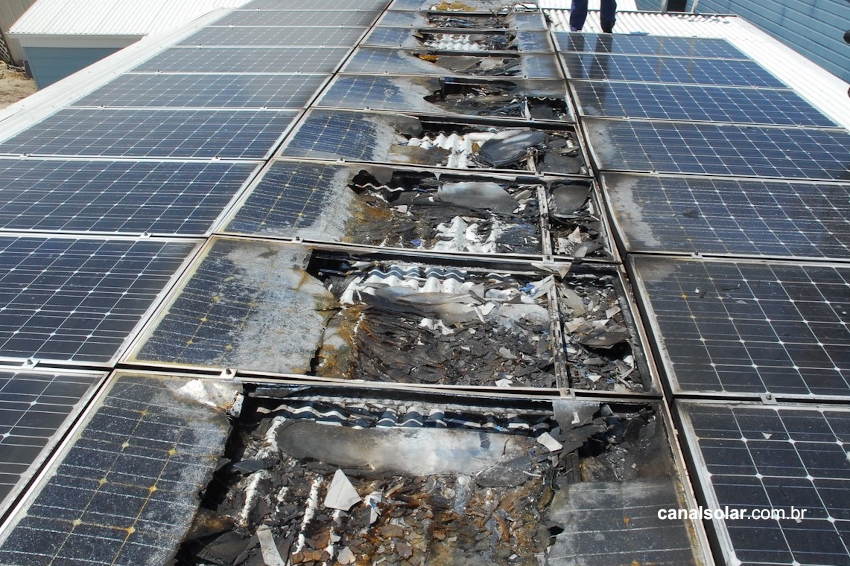
The photovoltaic cell behaves like a diode in these situations and this causes reverse current to flow into the faulty string. Depending on the intensity of this current, the module may overheat, posing a risk of fire and accelerated component degradation.
If the voltage difference is sufficient for the reverse current to appear but not high enough to force a system shutdown, the inverter may still continue operating, but with significantly reduced efficiency and compromised safety.
Other types of electrical and installation faults can lead to a reduction in the open circuit voltage of a string and subsequent emergence of reverse current in parallel-connected systems. The most common failures are:
- Short circuit in one of the modules;
- Short circuit between module cells;
- Module ground faults;
- Installation errors causing strings in parallel with different numbers of modules.
An example of the severity of the error and the risks of installing strings of different sizes in parallel was shown in the article Case Study – Fire in photovoltaic solar inverter. Although electrical faults leading to open circuit voltage difference of strings do not occur frequently, appropriate preventive measures must be taken in order to reduce the risks.
These electrical faults are dangerous and have a high potential to cause damage, as all modules in the affected string can be damaged. Overheating of modules and cables can cause accelerated equipment degradation and can even cause fires.


It is common to hear that the bypass diode (present in the junction box of the photovoltaic module) can help prevent reverse current, but this information is wrong. The bypass diode only acts to reduce the effect that shading produces on the module and has little relationship with the string's open circuit voltage variation. To prevent or limit reverse current in strings we must look for other solutions, such as those discussed below.
Diodes in series with the strings
The diodes in series with the strings are installed in series with the modules and aim to block any contrary current flow. This makes it impossible for reverse current to occur. However, this solution has a disadvantage: the diode is always connected and carrying current and this leads to continuous losses due to heat dissipation in the component.
Furthermore, a defect or failure in a diode can cause the loss of its safety function (for example, if it is short-circuited or a power surge has damaged its internal structure) or the string will be disconnected.

Fuses in series with the strings
String fuses are connected in series and can limit the reverse current when it reaches the fuse actuation value. For example, in a circuit with 4 strings in parallel where the normal operating current does not exceed 10 A per string, a 15 A fuse per string is installed.
These fuses are fundamental to the safety of photovoltaic systems, being mandatory by rule for arrangements with three or more parallel strings, vital knowledge that can be obtained in Canal Solar solar energy courses.
The fuse will blow and interrupt the current if it reaches 15 A or more in a string, which should not occur in normal operation, but may occur with faults that cause reverse current. If this circuit did not have this fuse, the reverse current could reach values of up to 30 A (10 A per string in parallel), causing a high risk of fire and damage.

Series fuses are the standard solution for photovoltaic systems and mandatory for arrangements with three or more parallel strings. The conduction losses that string fuses cause are much smaller than the losses with string diodes. Some inverters even have fuse boxes attached to their housing and electronic devices capable of detecting whether the fuses are functioning normally.
The components of the photovoltaic system (modules, cables and connectors) must be chosen taking into account the maximum reverse current that a fault can cause in the strings and the level of reverse current protection that the system has. In the module's technical data we can even find the maximum reverse current that a module can safely support.
Most photovoltaic modules on the market support reverse currents of around 15 A to 20 A — even so, this current must be avoided and the strings must be properly protected by fuses with breakdown currents below 15 A.


References
[1] Reverse Current Advice on generator configuration for PV systems using Sunny Mini Central, SMA
[2] Large scale PV systems under non-uniform and fault conditions, Solar Energy, Volume 116, June 2015, Pages 303-313


4 Responses
Help me, when I place the solar plate far from the lamp, it discharges instead of charging...this has been driving me crazy.sos
Good afternoon! I would like an example of how to connect 2 arrays of modules to the same MPPT input. I would also like you to inform me if there is a way to install a 100 kW system, just by connecting the panels in series. Thanks!
Good afternoon! I would like an example of how to connect 2 arrays of modules to the same MPPT input.
Congratulations and thanks for the article!