
The most common supply voltages in Brazil today are 127/220 V and 220/380 V, however, they are not the only ones historically available.
In the past, 110/220 V or 115/230 V supply voltage was common in much of the Southeast, and although there has been an effort to standardize all 110/220 V connections to 127/220, there are still locations and applications specifications that use the old standard.
The 110/220 V voltage is commonly confused with the 127/220 V voltage to this day.
Origin of the 110/220 system and differences from the 127/220 systems
The energy distribution system operates with three distinct phases, where each phase behaves like a 60 Hz sine wave.
At the three-phase system, these waves are delayed from each other, so that the peak values of each phase occur with a delay of 5.55 ms. We can also say that these waves are out of phase by an angle of 120º.
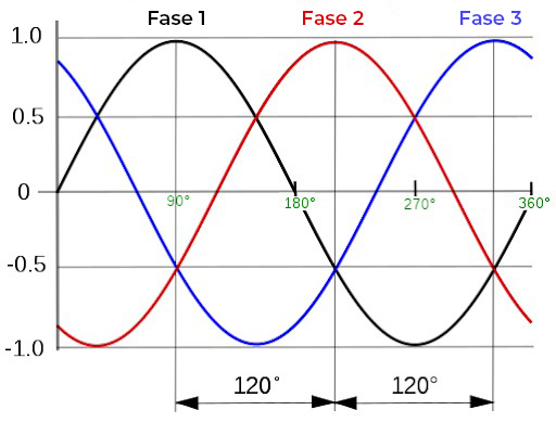
Using the neutral as a reference point, we can measure the voltage of each of the separate waves. One phase of a 127/220 system measures, from its peak to the reference point, 180V.
However, we usually deal with voltage and current values in “average” terms, called effective value (RMS – Root mean square – root of the mean of the squares), from which 127 V arises (which is the effective phase voltage value).
If instead of using the neutral as a reference, we connect the measurement between one phase and any other phase, we will measure a difference of up to 310 V, which is equivalent to an effective voltage of 220 V.
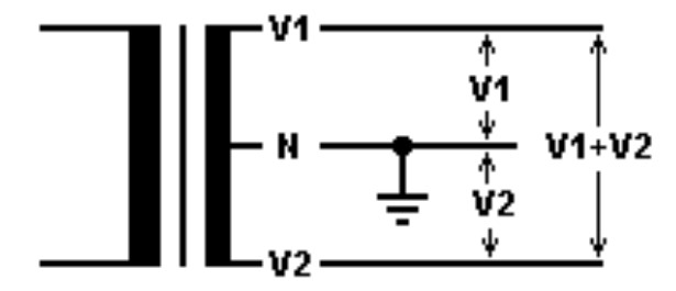
The 110/220 systems operate differently. In the 110/220 system, the phases are 90º or 8.8 ms behind each other, which means that the voltage measurement between two phases is always twice that measured between the phase and neutral.
This type of system is known as split phase or split phase. The phases can be obtained by a single-phase transformer, as long as the “neutral” point between the phases on the low voltage side is exactly the middle point of the windings on the secondary side.
This type of system can save cables and transformers, and is also commonly used in MRT systems or rural electrification lines of long distances and low power.
This type of system does not apply to three-phase networks, and, due to an effort to standardize supply voltages, it is difficult to find outside the scenarios of MRT systems, rural lines or small sectors within cities that have not yet been standardized.
Split-phase grid inverters
Most residential single-phase inverters work with a voltage of 220V. In 127/220 systems, they are connected between two distinct phases, thus obtaining 220V for operation. In the same way, you can connect the single-phase inverter between the two phases of the 110/220 V system, since the inverter will only use the voltage difference between these phases as a reference.
Although rare, there are two-phase inverters that require two phases and neutral. If this is the case, it will not be possible to use an inverter for 127/220 networks in a network with a 110/220 V system, as the inverter may interpret the phase difference as a network failure. For these specific situations, we must use an inverter suitable for split two-phase networks.
Split-phase hybrid systems
Another scenario where split-phase systems may appear are hybrid systems. Hybrid systems commonly rely on an internal AC output to power critical loads. Most hybrid systems have a 220 V single-phase network at their output, however, depending on the loads, it may be necessary to supply more than one phase.
An alternative to this problem is the implementation of a split-phase system within the inverter, that is, an inverter capable of supplying a two-phase circuit of the type 110/220 V, 115/230 or 220/440 V for example.
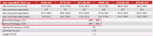
To illustrate this application, we will consider the Afore AF3-9.6K-DH family of inverters. This family of inverters can work with two-phase split-phase grids at their input and, being hybrid, can power loads connected to their output AC bus during a grid power outage.
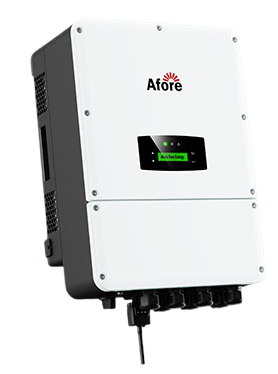
This specific model also features split phase in its AC backup network, providing the loads with two phases and a neutral, thus being able to supply single-phase and two-phase equipment with 120 and 240 V. In other words, a single equipment can generate the network for single- and two-phase loads during a power outage.


6 Responses
I bought a 220v hybrid inverter but in my house I have 110v and 220v, how do I connect the inverter so that it sends 110v
Would anyone have any insight into the DPS connection in this system with MRT transformers? I ask this because of the transient voltages that can come from this neutral and the risk of making a TN-S grounding for this.
The problem I encounter is specifying the type of grounding to be done for the correct dimensioning of the DPS. Because this power supply is provided by an MRT TRAFO, I am afraid of creating a TN-S scheme, due to the possible transient voltages that usually appear in the X0 that comes out of this transformer (the controversy that surrounds this type of transformer due to the grounded neutral on site…)
Therefore, I assume that the best option would be to adopt a TT grounding scheme and start connecting the DPS that corresponds to this scheme.
Could you shed some light?
How should I buy this inverter?
I have tension 110 and 220 03 phase and 01 neutral
I need a three-phase solar inverter 127/220 of 25W or 30W, do you have the option to sell me one?
A 220V single-phase inverter can be connected to a 120/240V network. Here in my region, the dealership offers this voltage in Delta with neutral.