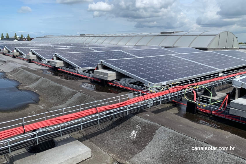
A grid-connected photovoltaic system is simply composed of a set of photovoltaic modules, DC cabling, string box with DC protections, inverter, AC cabling and AC protection.
Standards NBR 5410, 5419, 16612 and 16690 determine the protection criteria that a photovoltaic system must have, both in its AC part and its DC part.
The set of standards provides that installations must have as basic characteristics protection against electric shock to the user, protection against thermal effects and fires, protection against overcurrent, protection against overvoltage and sectioning capacity.
This article will explore how to determine the cable section and the overcurrent and short circuit current protection components of a photovoltaic system in order to guarantee thermal and fire protection of the cables.
Thermal effects
A current passing through a conductor generates heat through the Joule effect. The heat generated in the conductor is proportional to the square of the current, the resistance of the conductor and the time the conductor is carrying that current. We can then write:
Q = I2.Rt
Where:
- Q is the heat generated by an electric current passing through a given electrical resistance for a given time, measured in Joules;
- I is the electric current that passes through the conductor with a given resistance R;
- R is the electrical resistance of the driver;
- t is the duration or interval of time in which the electric current travels to the conductor.
The resistivity or resistance R of a conductor can be calculated as:
Resistivity = ρ. THERE
Where ρ is the resistivity of the conductor material, L is the conductor size and A is the conductor section. We can then notice that increasing the conductor section reduces the resistance of the cable, which in turn reduces the heat generated in the cable.
Conductors have the capacity to dissipate heat generated by the Joule effect into the environment, however, this capacity can be affected by the ambient temperature, grouping of nearby circuits, the method in which the conductor is installed and the thermal resistivity of the soil, if the same is buried. If this dissipation is insufficient, the cable will heat up and could eventually start a fire.
NBR 16690, the standard that regulates photovoltaic systems, indicates that all conductors in photovoltaic systems must be sized following the precepts of standards NBR 5410 and NBR 16612 (specific cables for solar applications).
Throughout the article, we will explore how the cables of a photovoltaic system should be sized and the relationship between sizing and system protection.
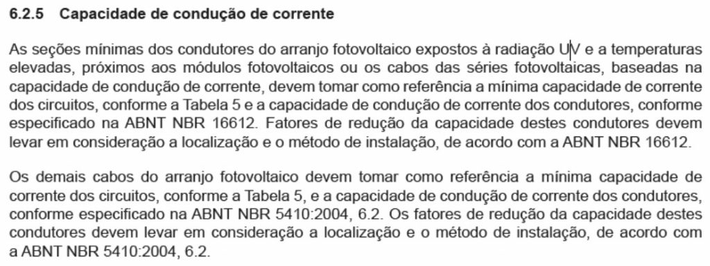
Regarding cable sizing, the NBR 16690 standard states:
 Therefore, the definition of current carrying capacity to be followed depends on which section of the circuit is being analyzed.
Current carrying capacity
All cables in a photovoltaic system must be sized to reduce the risk of overheating and fire. The sizing of a conductor must take into account the following electrical quantities:
- Design current – Ib: Wcurrent that a given circuit consumes or injects.
- Nominal chain – In: Wcurrent in which a particular device, cable or protection is designed to operate without risk of damage.
- Overload current: Current of a circuit operating on a continuous or prolonged basis above the nominal current In or the current carrying capacity Iz.
- Short circuit current – Icc: High momentary overcurrent that arises when there is a short circuit or electrical fault between conductors or between conductor and earth
- Current carrying capacity – Iz: Capacity of a cable to conduct current given its section, in such a way that the cable does not exceed the maximum temperature established in table 35 of 5410 or equivalent standard
To avoid overheating, the conductors must have a current carrying capacity greater than or equal to the design current Ib of the circuit they supply.
However, as previously mentioned, the ability of a cable to dissipate heat is dependent on the ambient temperature, grouping of nearby circuits, the method in which the conductor is installed and the thermal resistivity of the soil, if it is buried.
The NBR 5410 and NBR 16612 standards provide ways to recalculate the current carrying capacity based on these external effects.
Installation methods according to NBR 16612:
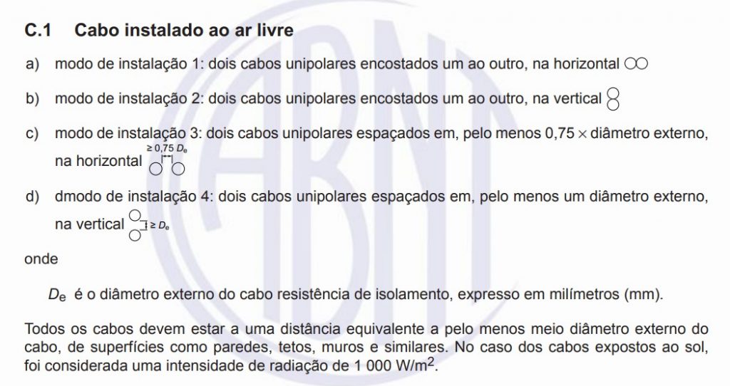 Cables that are exposed to UV radiation, high temperatures or that form photovoltaic series must follow the current carrying capacity given by the tables in Annex C of standard NBR 16612. For example, for cables installed outdoors we have: And the current carrying capacity for this type of installation is given by:
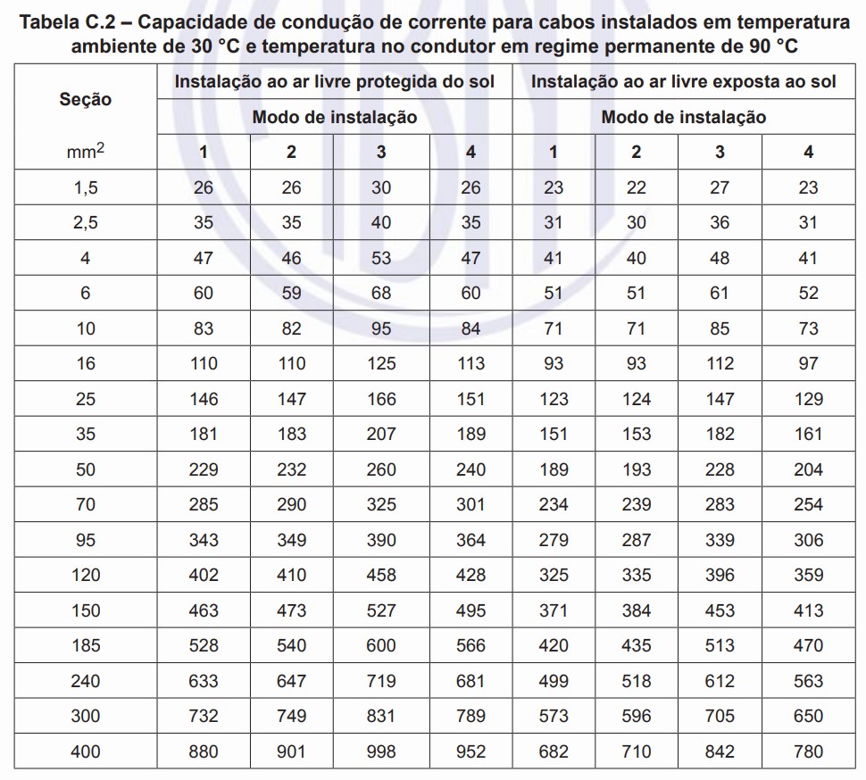
Table: Current carrying capacity according to NBR 16612, at an ambient temperature of 30ºC and a steady-state conductor temperature of 90ºC
 The grouping factor must be that defined by NBR 5410. NBR 16612 says, in section “C.5 Circuit grouping”: In case of circuit grouping, the grouping factors given in ABNT NBR 5410 must be used.
For higher temperatures and other installation methods, the other tables in Annex C must be followed. For the other cables in the system, we can follow the specifications of NBR 5410. The correction factors for current carrying capacity are:
- Ambient temperature factor – FOK
- An increase in ambient temperature decreases the cable's dissipation capacity, therefore decreasing its current carrying capacity.
Table 3: Correction factors for ambient temperatures other than 30ºC for non-underground lines and 20ºC for underground lines
 Soil thermal resistivity factor – FLOL
- For buried cables, the soil's ability to absorb heat is essential in terms of increasing the conductor's temperature.
 Soil thermal resistivity factor – F
Table 4: Correction factor for underground lines in soil with thermal resistivity other than 2.5 Km/W
 Circuit grouping factor – FB.C
- Bundled cables conduct heat between each other and make thermal dissipation through the air difficult.
 Circuit grouping factor – F
Table 5: Conductor grouping factor according to NBR 5410
 The corrected current carrying capacity (Iz') for a circuit is obtained by the formula:
Iz'=Iz * FOK *FLOL *FB.C
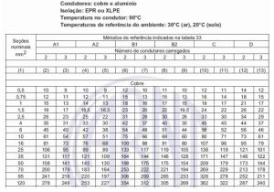
Where the Iz value is obtained from a table that relates the conductor installation method to the cable section.
Table 6: Current carrying capacity for EPR and XLPE type cables
 The relationship between overcurrent protection and reverse current
 The relationship between overcurrent protection and reverse current
The module can be approached by a current source proportional to solar irradiation. The STC test conditions determine the short-circuit current and open voltage of the module assuming an irradiation of 1000 W/m2 and cell temperature of 25°C.
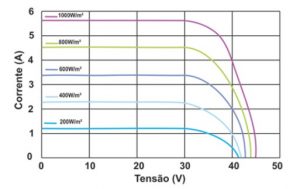
In a real installation, the cell temperature reaches around 30°C above ambient temperature, therefore, it is common for cells to reach up to 70°C during operation.
The increase in cell temperature has a subtle effect on increasing the module short-circuit current (Isc), in the order of +0.05% /°C. For an ambient temperature of 30°C, the increase in ISC in relation to STC conditions it is only 1.7%.
As in a real installation the maximum ambient temperature is limited and rarely exceeds 1000 W/m², the Isc current will never exceed significant values beyond the values determined in STC + 2%. Therefore, there is no need for protection against overcurrent due to a possible increase in the module's generation.
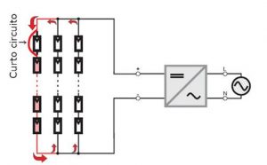
Overcurrent protection through a fuse or circuit breaker has the main function of preventing reverse current flow from occurring.
Reverse current occurs in a module assembly with strings in parallel when the open circuit voltage (Voc) of one string is lower than the open circuit voltage of the other strings.
When this occurs, the string affected behaves analogously to a system load, dissipating the heat generated by this reverse current passage. The most common causes of reverse current are:
- Short circuit in one of the modules;
- Short circuit between module cells;
- Module ground faults;
- Installation errors causing strings in parallel with different numbers of modules.
To learn more about reverse current, read our article on the topic, available at: Causes and effects of reverse current in photovoltaic modules
Sizing of overcurrent and reverse current protection devices
gPV type circuit breakers and fuses can be used as protection devices against overcurrent and reverse current in photovoltaic arrays. Details of each of these components can be found in the article Understand the basic specifications of the String Box components
Protection against overcurrent in a series is only mandatory if the current of the modules in which the series is in parallel is greater than the maximum reverse current supported by the analyzed series.
So, for example, a series that contains modules that have a maximum supported reverse current of 15 A and Isc current of 9 A can be paralleled with an identical series, without the need for a circuit breaker or fuse.
However, it cannot be parallelized with 2 or more series without the use of protection because, if a reverse current occurs, the series does not have the capacity to withstand it without posing risks (reverse current possible with two more strings in parallel: 18 A, maximum supportability of the analyzed string: 15 A)
The overcurrent protection device, when mandatory, must be sized in such a way that the nominal current of the device In, complies with:


○ 1.5*ISC < In < 2.4*ISC
○ In less than or equal to the maximum reverse current supported by the module (see datasheet)
When series junction boxes are added to a main junction box, a photovoltaic sub-array is formed, as shown in the figure below. The sub-array must also have overcurrent protection, with the protection device meeting the requirements below:
○Required if there are more than two series groupings connected to one inverter
○1.25*ISC Sub-arrangement < In < 2.4*ISC Sub-arrangement
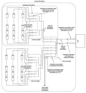
When the series junction box is connected directly to the inverter, a photovoltaic array is formed.
Protection against overcurrent of the photovoltaic array is only mandatory if there is a battery bank or any other source of current in addition to the photovoltaic system that could contribute to a harmful overcurrent. Protection, in these cases, is defined as:
1.25.ISC-ARRANJO < In < 2.4.ISC-ARRANJO
All cables must be capable of withstanding the rated currents of the protective devices connected to them.
In circuit sections where there is no overcurrent protection device, such as in cables that form the photovoltaic array when there are no external current sources or when use is not mandatory, the recommendations in table 5 of the NBR must be followed. 16690.
Table 7: Minimum section of conductors in relation to protection and use
 All protective devices must be capable of operating at the maximum voltages of the circuits to which they are connected.
Example
In this example, the cables will be sized for an arrangement of 180 BYD 370M6K-35 modules. The modules are placed on a table 90 modules wide by 2 modules high, with each string containing 18 modules.
The ten strings will be connected to a string box, where they will be parallelized. The parallelized circuit will be connected to the inverter via a buried cable.
From the module datasheet, we can obtain the short-circuit current, open-circuit voltage and the highest rated current of the series protection device possible.
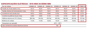
Each string will have 18 modules in series, therefore, 9.77 A of current Isc and 846 V of Voc. As the strings are connected in parallel in the string box, there needs to be overcurrent/reverse current protection in the series. Following NBR 16690, the nominal value of the overcurrent protection device must comply with:
○ 1.5*ISC < In < 2.4*ISC, therefore, 14.66 < In < 23.44 A
○ In less than or equal to the maximum reverse current supported by the module (see datasheet), therefore, In >= 15 A
The overcurrent protection device chosen must be between 14.66 A and 15 A, so in this example a 15 A fuse was chosen.
The modules must be connected to the string box with a cable that follows the NBR 16612 standard, as it is exposed to the weather and is part of a photovoltaic series. Immediately before the string box, the cables from all the strings will be sharing the same conduit, which was placed below the modules.
In this conduit there will be a grouping of 10 circuits at an ambient temperature of 40°C. The installation method is defined in section C.1 of standard 16612:
 The current carrying capacity is then given by the table below. (Table C.3 of the NBR 16612 standard – for an ambient temperature of 40ºC)
 The grouping correction factor is given by NBR 5410:
 The cable is installed using method 1, has a section of 4 mm² and is installed away from the sun, therefore, its current carrying capacity is 42 A. As the cable is grouped in a conduit with 10 circuits, the F cluster correctionB.C is 0.5.
Iz'= Iz * FB.C
Iz' = 42 * 0.5
Iz' = 21 A
As the corrected current carrying capacity Iz' is greater than the design current (current of each series) and greater than the nominal current of the protection device (fuse, 15 A), the 4mm² cable can be used safely .
The series paralleled in the string box have 846 V of Voc and 97.7 A. As the cables are buried and are not exposed to UV radiation, we can follow the NBR 16612 standard. In this example, we will consider that the soil temperature is 30°C and the thermal resistivity is 2.5 Km/W. The installation method for buried cable is, and the current carrying capacity table:
 For this example, it is not necessary to use an arrangement overcurrent protection device, however, when making this choice, the minimum current carrying capacity present in table 5 in NBR 16690 must be followed, which states that the cable must withstand at least 1.25 times the short-circuit current of the arrangement. The short-circuit current of the arrangement is 97.7, therefore the conductor must withstand at least 122.15 A.
To determine the minimum section of the conductor, the equation below is used.
Iz'=Iz * FTA * FRS * FAC
Like 122.12 <= Iz'
122.12 <= Iz * FOK *FLOL *FB.C
Iz >= 122.12/ (FOK *FLOL *FB.C)
Iz >= 122.12 / (1*1*1)
Iz >= 122.12 A.
From the current carrying capacity table, we then obtain that the minimum conductor section must be 50 mm².
This concludes the definition of cables and protections from the point of view of offering safety against overcurrents.
For a more in-depth understanding of the selection and sizing of cables and protections in photovoltaic systems, it is recommended to participate in solar energy courses and training, helping to ensure compliance with safety and quality standards.


3 Responses
I would like to know about the drop cable of a “AC side” micro inverter, can I use the same DC cable used in the strings?
Good afternoon. I am Bernardo Bimbe, Angolan and resident in Angola. I liked the information that is being provided on this page, especially the way it is being covered. I intend to learn a lot about the photovoltaic energy system. At the moment I have outlined below the themes that captivated me.
– Primary Cabin and Grid Connection
– Grounding and SPDA of Solar Plants
– Solar Energy Projects with Battery Storage
Very good content, high technical quality, adds more knowledge and security to professionals in the area.