Photovoltaic systems can have two types of diode: the bypass diode and the blocking diode. Although both are the same device, they fulfill very different functions. The two diodes solve common problems in almost all types of installation. The bypass diode (also known as the pass diode) aims to prevent the formation of hotspots (hot spots) in photovoltaic modules, while the blocking diode aims to prevent reverse current in strings connected in parallel.
The bypass diode and the hotspot problem
Photovoltaic modules are basically composed of cells connected in series. These modules are also connected in series to form strings. Therefore, we have hundreds of cells connected in series in a string. This means that, regardless of the shading situation, the current flowing through the cells is the same at all times. However, when only a portion of the cells in the string are shaded, the short-circuit current level of those shaded cells drops. Any current passing through a cell at a level above its short-circuit current causes the cell to overheat. This localized overheating (hotspot) can permanently damage the cell.

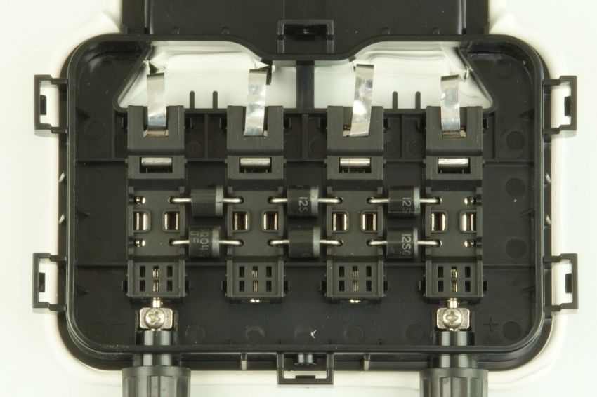
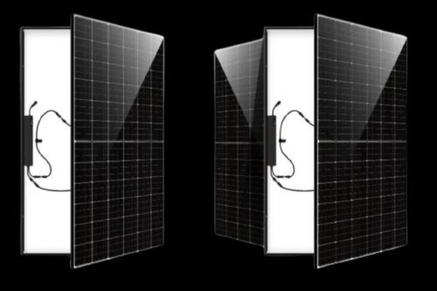
To avoid the formation of these hot spots, which damage the cell and permanently compromise the system's performance, bypass diodes are added to the modules during the manufacturing process. There are usually three or four per module. Each bypass diode is in parallel with a certain number of cells. For example, in 72-cell modules there is a bypass diode for each group of 24 cells.

The blocking diode and the reverse current problem
Reverse current is that which flows in the opposite direction of the photovoltaic module's energy supply. When subjected to reverse current, the solar module stops being a generator and becomes an energy receiver. Although rare, this effect can occur in systems with many strings connected in parallel. When we have an arrangement with strings in parallel and one of the strings suffers strong shadowing or has a defect, the other strings can see the shadowed string as a load and inject their current reversely through it. This reverse current permanently damages the photovoltaic module if it exceeds the maximum value specified in the catalogue.

To prevent the modules from being damaged, blocking diodes could be connected, as shown in Figure 5. These diodes aim to ensure that the current only flows in the correct direction, and never in reverse in the modules.

It is important for the reader to understand the operation and function of the blocking diode. For people who are starting to learn about photovoltaic systems, confusion between the blocking diode and the bypass diode is common. They are diodes with completely different functions. While the bypass diode protects the module against hotspots during normal operation (i.e., when the module is supplying power), the blocking diode is added externally to the module, with the function of protecting it against reverse current. Although it can be an effective solution against reverse current, the presence of a blocking diode makes photovoltaic installations more expensive and complex. Furthermore, due to the voltage drop across the diode, these devices cause conduction losses that accompany the photovoltaic system throughout its operating time. In summary, the blocking diode reduces the overall efficiency of the photovoltaic system and its use should be avoided. Blocking diodes have been replaced by fuses in modern photovoltaic systems. The stringboxes of photovoltaic systems are equipped with fuses connected in series with each string. In place of a diode blocking the current there is a fuse that can burn if a reverse current occurs. This solution is cheaper and presents fewer losses, with the only inconvenience of having to replace the fuse when a reversal situation occurs. Fortunately, these situations are rare and only occur in abnormal situations. To size the fuse against reverse current, the designer must pay attention to the photovoltaic module datasheet. It is possible to know the maximum reverse current supported or the maximum value of the fuse that should be used. As an example, we have BYD's 360 Wp to 385 Wp monocrystalline family (M6K-36-SERIES-5BB), where the short-circuit current varies from 9.73 A to 9.86 A. And the nominal current value maximum fuse is 15 A.

References
- [1] MELO, KB ; MOREIRA, HS ; MOREIRA, AVS; WALLIN, F.; VILLALVA, MG Influence of Backtracking at Solar-Tracking Photovoltaic Power Plants for Generation and Protection. In: 11th International Conference on Applied Energy, 2019, Västerås. 11th International Conference on Applied Energy, 2019.
- [2] MOREIRA, AVS Performance of the Perturb and Observe Method with Adaptive Step and Point Grouping in a Photovoltaic Module with Intelligent Pass Diode in the Face of Partial Shading. Master's Thesis, UFRN, Natal, 2019.
- [3] BYD. MONOCRYSTALLINE M6K-36-SERIES-5BB. Version 1.0.2019. http://www.byd.ind.br/wp-content/uploads/2020/03/M6K_36_SERIE_5BB_pnl_solar_byd_01_0203202.pdf. Accessed on 08/28/2020.






One Response
Gentlemen, I am studying solar panels and solar generation, but I came across the situation that some companies' energy meters can detect that the customer is generating energy and also charge for what he is generating, for example he is producing 2000w, and the house consuming 1000w, theoretically it is injecting 1000w into the grid but the meter will calculate it as a consumption of 1000w, double loss, could the diode solve this problem of not injecting into the grid? How to solve this case so as not to inject anything? Another question that I don't understand is that it seems to break the wave into half a wave, I don't understand, how to solve this case?