

The insulation resistance test is an electrical safety test that aims to verify whether a photovoltaic system offers adequate insulation between its subsystems and the external environment. This way, it is also possible to check the integrity of conductors and equipment, in addition to detecting degradation and failures in conductor insulation.
O electrical insulation resistance test is one of several ways to detect or predict conductor failure in a photovoltaic system. The “Megger” test, as the isolation test is often called, is a registered trademark of a product from a company that pioneered this specific type of test [1].
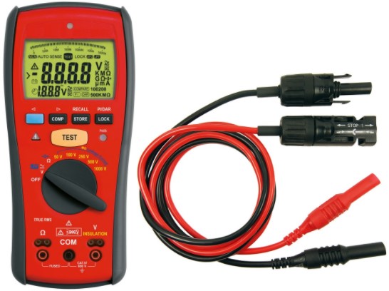
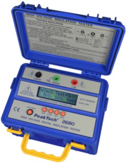
Generally, the equipment used in this test is called a megohmmeter. This equipment is capable of measuring electrical resistance by injecting a pulse of current onto two terminals of an electrical circuit. Megohmmeters can supply high DC voltages (from 500 V to 15 kV, depending on the equipment). Suitable insulation resistances are around 1 MW at 10MW, depending on the application.
What is a lack of insulation?
Lack of insulation occurs when two or more parts of a system with different potentials (voltages) come into contact with each other or with a grounded part. This normally occurs due to insulation failure. For example, a fault of this type can occur when two bare conductors touch each other or when a conductor comes into contact with a metal enclosure connected to earth.
A fault can be direct or indirect. A direct foul occurs when the parties touch and actually make physical contact. An indirect fault occurs when there is no physical contact between the conductors and the connection between the parts is made by an electric arc.
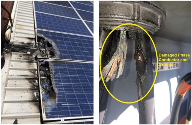
When one of the parties involved in the fault is the earth terminal, we speak of a fault to earth. A short circuit is a direct fault between live conductors, i.e. phases and neutral. A ground fault can result from an insulation failure, with ground faults and arc flashes being the most common reasons for fires in photovoltaic arrays [1].
In photovoltaic systems that use a transformerless inverter, the DC circuits are isolated from the earth. Modules with defective insulation, exposed conductors or an internal inverter fault can cause a DC current leak to earth (protective earth). This failure is also called insulation failure [2].
Leakage current is the current that, due to imperfection of the insulation, flows to the earth or to conductive elements foreign to the installation. It is important to note that in practice there is always a leakage current in any circuit, since there are, strictly speaking, no perfect insulators. However, under normal conditions, leakage currents are extremely low (only detectable by very sensitive ammeters) and do not cause problems with the installation [3].
AND It is necessary to test insulation resistance to ensure electrical safety, showing sufficient insulation between the electrically conducting components and the structure of the photovoltaic module, or between the photovoltaic module and the external environment. Inadequate insulation can cause electric shocks and other hazards.
Insulation resistance tests are used to verify and demonstrate the integrity of electrical wiring and equipment. These tests can also be used to assess degradation or damage to wiring insulation and locate faults within photovoltaic arrays and other system circuits.
Insulation resistance tests are an important element in the commissioning stage, acceptance tests and preventive maintenance for photovoltaic systems.
Identifying an insulation failure
Every time an inverter goes into operational mode and starts producing power, the resistance between ground and direct current conductors is checked. The inverter displays an insulation error when it detects a total combined insulation resistance less than a certain value.
An insulation failure may disappear and reoccur after a short period, for example when caused by morning damp. Therefore, it is recommended to resolve the problem as soon as it occurs, before it can temporarily disappear.
Electrical conductors are usually insulated with an outer covering to protect them from coming into contact with people, equipment, or other conductors. When conductors are exposed at termination points or busbars, terminal spacing and air gaps provide insulating properties.
The quality of the conductor insulation can be determined by measuring its resistance. Insulation resistance is determined by applying a constant test voltage to a conductor and measuring the current flow between the conductor and ground (or between other de-energized conductors in the system). This test is analogous to the pressure test in a hydraulic system to detect water leaks.
What do the standards say?
The technical standard ABNT NBR 5410 – Low voltage electrical installations [4] determines that electrical installation insulation resistance tests must be carried out when relevant. Item 7.3.3 of the standard determines that the insulation resistance must be measured between each live conductor and the earth and between live conductors, taken two by two.
In the case of photovoltaic systems, there is nothing to discuss regarding the relevance of insulation resistance tests. The technical standard ABNT NBR NBR 16274 – Grid-connected photovoltaic systems – Minimum requirements for documentation, commissioning tests, inspection and performance assessment [5] determines that the insulation resistance test for DC circuits must be applied. To prepare the ABNT NBR 16274 standard, the text of the standard was taken as a basis IEC 62446-1 [6].
Subsections 6.7 and 8.3 of ABNT NBR 16274 are dedicated exclusively to this topic. Subsection 6.7 describes the method and procedures for the insulation resistance test of the photovoltaic array, in addition to the safety measures to be followed.
While subsection 8.3 describes a wet insulation resistance test procedure, which evaluates the electrical insulation of the PV array (module assembly) under wet operating conditions.
When to carry out an insulation resistance test?
As the insulation of conductors degrades, their insulation resistance decreases. The higher its insulation resistance value, the better the insulation quality of the conductor. Excessive leakage currents can present a risk of electric shock, damage equipment and impair system performance.

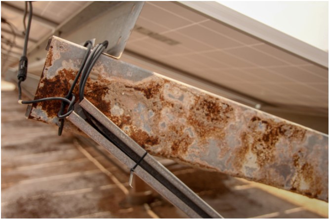
Additionally, a ground fault can result from a failure in the insulation that isolates current-carrying conductors from contact with grounded conductive surfaces. Damage to conductor insulation may result from improper installation or environmental factors, including impact or vibration, animals or insects, or deterioration caused by temperature or sunlight, or other adverse conditions.
Because degradation of photovoltaic modules and wiring systems over many years of direct exposure to the elements, older photovoltaic panels will naturally have lower insulation resistance than when they were new. Insulation resistance tests are recommended at a 3-year maintenance interval or more frequently as circumstances require.
A wet insulation resistance test is normally carried out when the results of a test in dry conditions are inconclusive or questionable. This test is also normally carried out when insulation failures are suspected due to manufacturing or assembly defects in the PV array.
How to carry out an insulation resistance test?
There are two methods for carrying out an insulation resistance test:
- Method 1: Short-circuit the positive and negative terminals of the photovoltaic string (set of modules in series) before measuring the insulation resistance between the short-circuit point and ground;
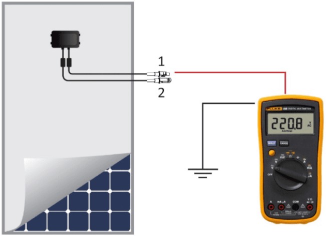
- Method 2: Measure the insulation resistance between the positive electrode and ground, and then between the negative electrode and ground separately, without short circuit.
Both methods are described in the standard IEC 62446-1, so both can be used. However, when applied to photovoltaic strings, both methods present problems that we consider below.
A photovoltaic module behaves like a limited current source, so it is not a problem — from an electrical point of view — to short circuit the positive and negative terminals. Once the terminals are shorted together, the insulation resistance can be correctly measured using insulation resistance meters (megohmmeters).
However, close attention must be paid when short-circuiting the terminals of photovoltaic strings. This method presents an accurate but dangerous way of measuring insulation resistance. The best alternative when using the short circuit method is to measure the insulation resistance at night when the photovoltaic modules are turned off.
The second method of testing insulation resistance does not employ shorting the terminals. With this method the risk of electric shock will be minimized. On the other hand, with this last test there is a risk of obtaining incorrect measurement values due to the test method used by insulation resistance meters. This is caused by the electrical potential existing in the photovoltaic module.
Insulation resistance meters in general are designed to measure an object that has no electrical potential. When electrical potential is present, the measured value may be greater or less than the actual value, depending on the measurement conditions.
In summary, when measuring the insulation resistance between the positive electrode and ground, the meter will detect a higher current due to the additional current generated by the PV module and calculate an insulation resistance lower than the actual value, resulting in a false negative.
On the other hand, when measuring the insulation resistance between the negative electrode and ground, the directions of the measured current and the current generated by the module will be opposite each other, causing part of the measured current to be canceled. As a result, the calculated insulation resistance will be higher than the actual value, resulting in a false positive [7].
Final considerations
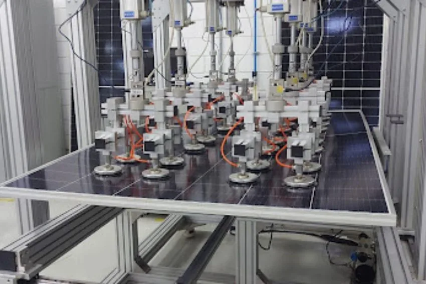
Currently, photovoltaic module manufacturers use advanced testing machines that also test the module's insulation resistance. As this is an important safety aspect of the PV module, according to the standard IEC 61215, the insulation resistance test needs to be installed on each manufacturer's assembly line.
Before testing specific products and installations, including inverters and photovoltaic module strings, confirm the testing procedure with the manufacturer so as not to void warranties. Some module manufacturers explicitly disallow insulation testing. However, the most common locations for ground faults in photovoltaic systems are on modules and their conductors [1].
References
[1] National Renewable Energy Laboratory – NREL, Field Guide for Testing Existing Photovoltaic Systems for Ground Faults and Installing Equipment to Mitigate Fire Hazards, October, 2015. Available electronically at SciTech Connect http:/www.osti.gov/scitech.
[2] SolarEdge, Application Note – Isolation Fault Troubleshooting, December, 2017.
[3] Prysmian Group, Prysmian Electrical Installations Manual, 2010.
[4] Brazilian Association of Technical Standards, ABNT NBR 5410:2004 – Low Voltage Electrical Installations, 2004.
[5] Brazilian Association of Technical Standards, ABNT NBR 16274:2014 – Grid-Connected Photovoltaic Systems — Minimum Requirements for Documentation, Commissioning Tests, Inspection and Performance Assessment, 2014.
[6] International Standard, IEC 62446-1:2016 – Photovoltaic (PV) Systems – Requirements for Testing, Documentation and Maintenance – Part 1: Grid Connected Systems – Documentation, Commissioning Tests and Inspection, 2016.
[7] Industrial Automation Asia, Testing the Insulation Resistance of Photovoltaic Panels, September, 2018.


One Response
Good afternoon!
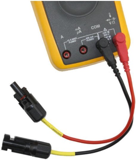
Could you indicate where we could purchase the Test Tip with the MC4 Connectors.
We have looked in many places, but we have not been able to find it.
Thanks,
Waldney Diógenes de Souza
SOLAR IRRIGAMINES