
A photovoltaic system connected to the grid is simply composed of a set of photovoltaic modules, DC cabling, string box, inverter, AC cabling and AC protection.
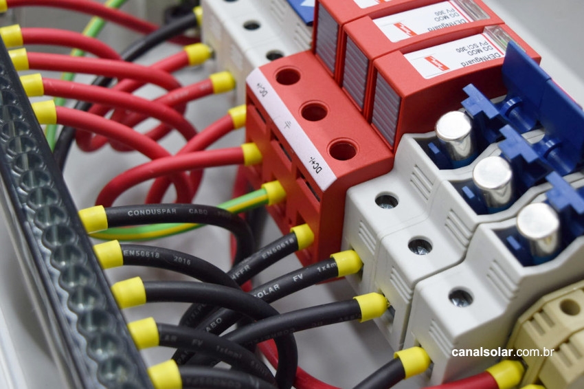
The string box
The Brazilian standard for low voltage electrical installations – NBR 5410 – and the Brazilian standard for photovoltaic systems – NBR 16690 – provide that the installations must have as basic characteristics protection against electric shock to the user, protection against thermal effects and fires, protection against overcurrent, overvoltage protection and sectioning capability.
Photovoltaic systems are included in the coverage of the standards, therefore they must follow the same basic principles. The string box is the protection component of the DC part of the photovoltaic system.
It connects the cables coming from the photovoltaic modules to the inverter, while providing overvoltage and overcurrent protection and allowing circuit isolation. The basic elements of a string box are:
- Enclosure – where the protection devices and electrical connections will be located;
- Disconnecting device – which can be implemented with a disconnecting switch or circuit breaker;
- Overvoltage protection device – DPS;
- Overcurrent protection device – circuit breaker or fuse;
- DC cables.

Components
Casing
The casing is the “box” where the protection devices and electrical connections will be located. The function of the casing is to protect the devices and connections from the weather and protect the user against electric shock.
The enclosure can be classified according to its tolerance of dust and water ingress. The IP rating system determines a number that reflects the protection of the enclosure. The table with IP protection settings is shown below.
Table 1 – IP degree of protection determination scheme

The enclosures can also be classified as suitable for internal environments (minimum IP2X protection) or external environments (minimum IP55 protection). ABNT NBR IEC 60529 is the standard that characterizes enclosures suitable for electrical circuits.
Installation standard 5410 also states that AC and DC circuits must not be mixed in the same enclosure. It is recommended that the maximum volume enclosure occupancy rate is up to 50%. This rate limits the effect of overheating when concentrating devices in a closed environment. Some examples of wrappers are shown below.

Disconnect switch
The disconnector switch is a device for connecting and disconnecting the DC part of the photovoltaic system. Safe system disconnection is one in which there is no risk of electric shock to the user and no risk of fire caused by sparks at the time of disconnection. The disconnector switches have the following technical characteristics:
- Isolation/operating voltage: is the maximum voltage between the electrical connection points that the switch supports;
- Operating current: is the maximum current that runs through the electrical elements of the switch;
- Usage specification: defines whether the key is suitable for AC or DC systems;
- Number of poles: is the number of conductors that the switch can section;
- Impulse withstand: the switch must be capable of withstanding an electrical impulse in the open position according to the specifications in table 50 of NBR 5410.
For each switch operating voltage value, there is a maximum operating current. Manufacturers make this information available in the product's technical brochure. To prevent sparking during normal operation of the switch, the voltage, current and application limits must be respected.

Some switches can simultaneously section several conductors, and can then assume a “general switch” characteristic of the string box.
DPS (Surge Protection Device)
The DPS is the device that reduces the effects of overvoltage on the circuit. The function of the DPS in the string box is to protect the inverter against overvoltages coming from the DC circuit. The phenomena that can cause overvoltages are: atmospheric discharges in the SPDA system and nearby atmospheric discharges that induce current in the DC circuit. DPS is characterized according to the quantities below.
- Type: The DPS can be classified as type 1, 2 or 3. The type 1 DPS is suitable for direct lightning strikes, the type 2 SPD is suitable for overvoltages induced by nearby lightning strikes and disturbances in the electrical network. DPS type 3 is suitable for protecting more sensitive electrical equipment;
- Uc: Maximum continuous operating voltage. It characterizes the maximum operating voltage that the DPS can withstand without its overvoltage protection being activated;
- Up : Protection voltage level. It is the maximum voltage between the DPS terminals at the moment it is active and carrying discharge current equal to In or Iimp. In other words, it is the maximum voltage that the circuits downstream (that is, after) the DPS receive;
- Iimp: Nominal protection current for type 1 SPD. It is the maximum protection current that a type 1 SPD can divert to protective earth. Iimp values typically occur in direct electrical discharges;
- In: Nominal protection current for SPDs of Types 2 and 3. It is the maximum value of current that the SPD of Type 2 diverts to protective grounding. The DPS must withstand this current for at least 19 activations;
- Icc or Isc: This is the maximum short-circuit current that a SPD with an internal fuse or mini-circuit breaker can withstand. In the event of a failure in the DPS, it must be capable of conducting the short-circuit current until it is interrupted by the DPS itself, or by other protection existing in the circuit;
- IMAX: This is the maximum current that a SPD can divert to protective earth. The ability to divert current when it reaches IMAX only occurs once. The DPS becomes damaged and cannot be reused.
To learn more about overvoltage protection read the article What is DPS and how is it used in photovoltaic systems .

Fuse
The fuse is a protection device against overcurrent and short-circuit current whose operating principle is the melting of a conductive element when the current exceeds its nominal value. The fuse has the following technical characteristics:
- Dimensions: there are different dimensions of fuses, which are a consequence of their type of use, current interrupting capacity and rated current;
- In: rated current. It is the current used for overcurrent protection calculations;
- Maximum interrupting current: This is the highest current that the fuse is capable of blocking. Values above this limit do not guarantee current blocking and also put the fuse at risk of fire;
- Operating voltage: is the highest voltage at which the fuse operates without damage or risk of malfunction;
- Actuation curve: is the curve that shows the time it takes for the device to act for each current value above the nominal;
- Type: specifies for which circuit/use the fuse is suitable. The table below shows the most common fuse types;
- Non-fusion current: maximum overload current above the nominal current value at which the fuse will not operate;
- Conventional time melting current: overcurrent that guarantees the fuse actuation within the conventional time specification (1 or 2 hours)
Table 2 – Fuse type

The curve that relates the actuation time of a given fuse to the current that flows through it is shown below:


The fuse will not operate while operating in the blue region. The red region indicates the operating points that cause the fuse to trip. For a current of 200% the nominal value, for example, the fuse will operate between 50 and 200 seconds. For the fuse described in the graph, the non-melting current is 150% the rated current.

The fuses suitable for photovoltaic circuits are of the gPV type and feature protection against short-circuit current and overcurrent. The PV designation refers to the fuses' ability to operate at DC current with voltage values typical of photovoltaic systems.
gPV type fuses also have a non-melting current of 1.13 times the nominal current and a melting current in conventional time (1 hour) of 1.35 times the nominal current. The minimum maximum interrupting current of a gPV fuse is 10kA.
Circuit breaker
The circuit breaker is a thermomagnetic device for protection against overcurrent and short-circuit current, and can also be used as a disconnecting element. The operating principle of the device involves heating a bimetallic sheet that deforms with temperature and a coil that generates a magnetic field. Above a certain limit, the deformation of the bimetallic sheet and the electromagnetic force generated by the coil will cause the internal contacts of the circuit breaker to disconnect. Both the heat generated and the electromagnetic force are proportional to the current flowing in the circuit breaker. Circuit breakers can be characterized according to the quantities below:
- In: Nominal operating current. This is the maximum current at which the circuit breaker operates without triggering its protection. Values above this current will cause the circuit breaker protection to be activated and the circuit to be electrically disconnected;
- Icu: Maximum short-circuit current interrupting capacity. It is the maximum current that the circuit breaker can act by separating the circuit. Values above this current do not guarantee the functioning of the protection and may cause a risk of fire;
- Actuation curve: defines the characteristic of the protection actuation time in relation to the intensity of the overcurrent;
- Operating voltage: defines the nominal operating voltage of the circuit breaker;
- Circuit type: defines whether the circuit breaker is suitable for AC or DC circuits;
- Conventional time actuation current: current at which the circuit breaker guarantees disconnection in 1 hour.
The typical trip curve for a circuit breaker is shown below as an example.

The area in blue is the normal operating zone of the circuit breaker. There must be no protection or sectioning of the circuit in this area. The region in red is the zone in which the circuit breaker will act, with time depending on the proportion between the current passing through the device and the rated current. For a current of 10x the rated current, for example, the circuit breaker will trip between 0.01 and 2.5 seconds.
Circuit breakers can replace the use of fuses in a photovoltaic system. To do this, it must have an operating current in conventional time of 135% the nominal current of the device. The AC type circuit breaker does not have the same insulation and arc interrupting capacity as a DC circuit breaker, therefore, they should not be used in the string box.
DC cable
The string box receives the DC cables coming from the modules and makes DC cables available to the inverter. Therefore, the same care when selecting a DC cable for the module circuit must be taken when selecting the DC cables for the string box.
The cable must contain double insulation, be resistant to UV radiation, be capable of withstanding the DC voltages of the photovoltaic system (typically 600 to 1500 V) and must have a tinned copper conductor if it is in areas subject to salt spray.
The cable section depends on the installation method, circuit current, ambient temperature, circuit grouping and, if buried, soil thermal resistivity and soil temperature. The determination of the cable cross-section must follow standards NBR 16612, NBR 16690 and NBR 5410.

Connectors and connections
Connections between the string circuit and the string box can be made using MC4 connectors or through cables terminated in eyelets. It is not permitted to parallelize or connect multiple circuits to the terminal of a string box device if it is not specifically designated for that purpose. These connections must be made using buses or terminals suitable for this purpose.
Inappropriate connection of circuits generates hot spots on the cable, protection device and terminals. Hot spots increase system losses and can become fire spots.

The relationship between circuit breaker, fuse, overcurrent protection and reverse current
The module can be approached by a current source proportional to solar irradiation. The STC test conditions determine the short-circuit current and open voltage of the module assuming an irradiation of 1000 W/m2 and a cell temperature of 25°C.
In a real installation, the cell temperature reaches around 30°C above the ambient temperature, the increase in cell temperature has a subtle effect on increasing the module's short-circuit current, in the order of +0.05% /°C. For an ambient temperature of 30°C, the increase in Isc compared to STC conditions is only 1.7%.
As in a real installation the maximum ambient temperature is limited, the current Isc will never exceed significant values beyond the values determined in STC + 2%. Therefore, there is no need for protection against overcurrent due to a possible increase in the module's generation.
Overcurrent protection through a fuse or circuit breaker has the main function of preventing reverse current flow from occurring. Reverse current occurs in a module set with strings in parallel when the open circuit voltage (Voc) of one string is lower than the open circuit voltage of the other strings.
When this occurs, the affected string behaves analogously to a system load, dissipating the heat generated by this reverse current flow. The most common causes of reverse current are:
- Short circuit in one of the modules;
- Short circuit between module cells;
- Module ground faults;
- Installation errors causing strings in parallel with different numbers of modules.
To learn more about reverse current, read our article on the topic, available at: Causes and effects of reverse current in photovoltaic modules .


6 Responses
Very good content! Treats all significant points about the string box. I just thought I needed to talk a little about the cases in which not using the string box is recommended.
Hello, Eduardo, how are you? The cases in which non-use will be indicated will be when the inverter has all the necessary protections.
I would really like to learn and know everything about string box from 1 entry to multiple entries.
I work with electrical energy, and I intend to improve myself with solar energy and improve my knowledge in this area.
Beautiful to have you. We are guiding. Thank you and congratulations.
I am a mechanical engineer graduated from FEI in 1991
Electromechanical Technician graduated from ITF GO in 1986.
I have been working with air conditioning since 1989
I have worked with solar heating for 20 years and I am 52 years old.