

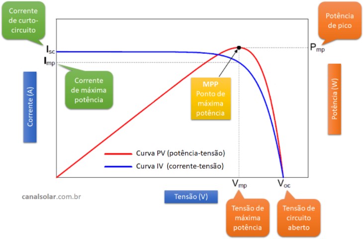
This article aims to clarify the characteristics of photovoltaic modules through the IV and PV curves. Curve IV is the graph that relates the current (I) and the output voltage (V) of the photovoltaic module. The PV curve is the graph that relates the power (P) and the output voltage (V) of the module. Isc (short circuit) is the maximum electrical current that the module can provide. Voc (open circuit – open circuit voltage) is the maximum voltage that the module can provide. Imp (maximum power) is the current that the module provides when operating at its maximum power point. Vmp (maximum power voltage) is the voltage that the module presents at its terminals when operating at its maximum power point. The name Pmp (maximum power) is a bit redundant and means exactly that. In other words, this is the peak power of the photovoltaic module. The MPP (maximum power point) is the maximum power point of the photovoltaic module. It lies at the knee of the IV curve and the peak of the PV curve. The values of Isc, Voc, Imp, Vmp, Pmp are specified in the data sheets for an irradiance of 1000 W/m² and an operating temperature of 25 °C.
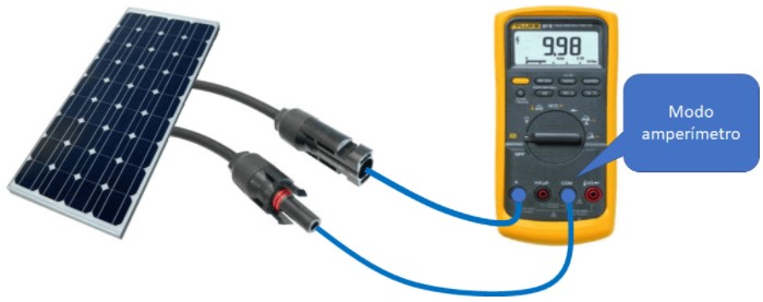
The figures below illustrate how the Isc and Voc parameters are measured. The short-circuit current Isc is measured with a ammeter, short-circuiting the output terminals of the photovoltaic module.
During the test illustrated in the figure below, the module is short-circuited internally by the multimeter (operating in ammeter mode).

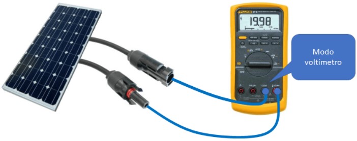
The open circuit voltage Voc, in turn, is measured with a multimeter operating in voltmeter mode, keeping the photovoltaic module terminals open.
Although they are connected to the multimeter during the test, there is no current passing through the module's output terminals, therefore we say that it is open circuit (off).


4 Responses
Hi, this information always appears in my application, which means what?
The photovoltaic capacity you fill has a large power deviation in the inverter
This guy knows a lot about this. As a student, you had to apply yourself to reach this level.
Dear Marcelo, good afternoon!
One doubt: Most Multimeters present a current measurement of a maximum of 10A (exactly as in the figure), but the most powerful modules have an ISC current above 10A.
What is the most suitable model that you would recommend?
Yours sincerely
Geraldo (85) 999991295
Excellent explanation, very summarized and very detailed.