
I received the following query from a friend: “I have a request for a quote to commission 7 plants in the Northeast. These are plants from 100 to 500 kWp. As I have never done the commissioning, would you be able to guide me? To carry out the category 1 test list, what equipment do I need?”
This is a subject of utmost importance! How many professionals, small and medium integrators or installers, have the same question?
Many professionals in the solar market have never commissioned a photovoltaic system, don't know how to do it or simply don't know what it is. It's simpler than it seems. I'm gonna explain.
But before I go any further, I want to make this message very clear: you don't need expensive equipment to commission a photovoltaic system. You don't need a fancy solar panel tester or an expensive curve plotter. You will only need a few basic instruments that I will show you in this article.
What is commissioning?
According to Wikipedia, “Commissioning is the process of ensuring that the systems and components of a building or industrial unit are designed, installed, tested, operated and maintained in accordance with the owner's operational needs and requirements.. Commissioning can be applied to both new projects and existing units and systems in the process of expansion, modernization or adjustment. In practice, the commissioning process consists of the integrated application of a set of engineering techniques and procedures to verify, inspect and test each physical component of the project, from individual ones, such as parts, instruments and equipment, to more complex ones, such as modules. , subsystems and systems.”
In summary, now in my words, we can say that commissioning a system means carrying out a set of tests and procedures that ensure the correct construction and integrity of the components and systems of an engineering work.
A Wikipedia goes beyond: “Commissioning activities, in their broadest sense, are applicable to all phases of the project, from the basic and detailed design, supply and expediting, construction and assembly, to the delivery of the unit to the final customer, passing through , often, through an assisted operation phase”.
What was meant in the last paragraph, in my interpretation, is that we do not need to wait for a work to be completed to carry out commissioning. Commissioning can begin at the design stage. A poorly done project will result in poorly done work, outside of standards.
Why not nip the evil in the bud? And after the project, why wait for the work to be completed, if we can check the work as it happens?
Commissioning can be done step by step, following each stage of the execution of a work. Everything we said above applies to photovoltaic projects. I always say that a photovoltaic project is an engineering project. I am wrong? I do not think so.
Photovoltaic systems should be designed, assembled and commissioned under the guidance of qualified engineers and technicians. Unfortunately, the reality of the Brazilian market is different and very complex.
Many amateurs, people who were already doing things wrong in other areas, venture into the sale and installation of photovoltaic systems – often without a project, without knowledge, without tools and obviously without commissioning.
The commissioning of photovoltaic systems could avoid many of the problems found in Brazilian installations, anywhere in the country: non-standard electrical installations, wrong designs, circuits and inverters on fire, low generation performance, damaged modules, modules blown by the wind, noisy roofs and all sorts of complications.
NBR 16274 standard
The Brazilian standard NBR 16274: Grid-connected photovoltaic systems – Minimum requirements for documentation, commissioning tests, inspection and performance assessment initially determines that every photovoltaic system must be accompanied by minimum documentation (item 4 of the standard) with basic system information, system designer information, installer information, electrical diagrams and projects, component data sheets, mechanical and operating and maintenance instructions.
If a photovoltaic project presents itself with all the documentation listed above, there is a high chance of success in the inspection stages and electrical tests. In the absence of this documentation, the professional who carried out the commissioning must be aware of all possible and imaginable constructive, mechanical or electrical faults that may be found.
It goes without saying that the commissioning professional must be adequately trained and preferably exempt, without ties to the professional or company that designed or implemented the photovoltaic system.
After evaluating the documentation, standard NBR 16274 provides guidance on technical inspections and electrical performance assessment tests, which are divided into two categories, in addition to the group of additional tests:
- Category 1 test regime (item 5.3.2.1 of the standard):
“A category 1 test regime is the minimum sequence of tests that must be applied to all systems, regardless of scale, type, location or complexity.”
- Category 2 test regime (item 5.3.2.2 of the standard)
“A category 2 testing regime is intended for larger or more complex systems. All Category 1 test regime tests must have been performed, and the system approved, before Category 2 test regime tests begin.”` Category 2 tests, which are detailed in Section 7 of the standard, are basically the IV curve test, using a curve tracer, and thermographic analysis of photovoltaic modules and electrical circuits.
- Additional assays
“In addition to the standard set of tests described in the category 1 and 2 test regimes, there are also other tests that can be carried out in some circumstances. These tests are likely to be applied either due to a specific customer request or as a means of fault detection when other tests or operational anomalies suggest a problem that has not yet been identified by standard tests.”
According to the text of NBR 16274, category 1 tests are mandatory. Category 2 tests are optional and can replace some category 1 tests. Finally, there are additional tests, which the standard implies are dispensable. We will talk about category 2 trials and additional trials in another article.
Let's focus now on category 1 tests, which are our main objective and are the minimum requirements for any photovoltaic commissioning.
Category Testing Procedures
Category 1 tests are relatively simple and do not require complex equipment. Every photovoltaic installer should be instructed and qualified to carry out these tests.
Many problems with photovoltaic systems would be detected with just two tests that are part of category 1: open circuit voltage and operational (or short-circuit) current of the photovoltaic strings or modules.
Ground Continuity Test
The continuity test aims to ensure the correct passage of electrical current through the metal parts of the modules and fixing structures. The objective is to ensure that there is electrical continuity between these parts and the installation's grounding conductor.
This test can be done with the continuity test function present in most multimeters. A multimeter is an instrument that any technician should have in their toolbox. Even low-cost multimeters have a continuity test function.
Continuity testing can be done in parts, testing continuity between the modules, between the modules and the mounting rails, then between the rails and the terminal closest to the grounding conductor. Testing electrical continuity between the module frames and the grounding conductor would be the most recommended.

Polarity test
This test aims to detect the polarity of the string cables that reach the inverters. This test must be done before energizing the inverters. Basically this test aims to determine whether the positive and negative poles are marked correctly.
That is, if the red cable is positive and the black cable is negative. Or whether the two black cables (if they are the same color) are properly labeled as positive and negative.
What is used in this test is the DC voltmeter function of a simple multimeter. No sophisticated equipment is required for this test. The only important care is to ensure that the multimeter supports the maximum voltage available at the terminals to be measured.
Junction box test
What the standard calls a junction box is what we know in the market as a stringbox. Again it is a test that can be done with the DC voltmeter function of a simple multimeter. The test employs a procedure that allows identifying the connection of inverted strings.
Basically, the test procedure consists of connecting all the negative terminals of the strings of a stringbox in parallel, leaving the positive terminals open. This can be done by leaving the negative fuses closed and removing the fuses from the positive poles.
Then, the voltage between positive and negative of the first series is measured. The measured value is used as a reference for subsequent tests. Then, keeping one tip of the multimeter on the positive pole of the first string (used as a reference), measure the voltage obtained at the positive terminals of the other strings with the other probe.
If everything is correct, the results of all measurements (from the positive of the first string to the positive pole of the others) will be approximately zero.
Photovoltaic series: current measurement
This is a very simple test, like all the others. Its objective is to measure the electrical current passing through the strings. Two currents can be measured, at the choice of the commissioning professional: operating current (when the strings are in operation) and short-circuit current (when the string terminals are short-circuited.
The difference between the first and second tests is that to measure the operational current, the photovoltaic system must already be in operation, that is, the inverter must already be turned on and connected to the electrical grid.
If the system still doesn't work, or if you prefer to test everything before turning it on, the remaining option is to test the short circuit current. The operating current test can be performed with a clamp meter capable of measuring direct current.
The short circuit test can be done with the same clamp meter or with a common ammeter. In either case, great care must be taken when short-circuiting the strings.
In fact, the problem is not causing the short circuit, but opening it. When connecting the two poles of the string, the maximum current will flow through it, which depends on the momentary solar irradiance condition. When trying to open the circuit under load, an electric arc (a large spark) and a fire may result.
The solution is to carry a disconnector switch in your suitcase (the kind used in stringboxes) and close and open the short circuit using this switch. Never try to cause a short circuit manually or using the multimeter test leads.
As the string current depends on irradiance, you should try to do this test close to noon and preferably on a day with stable weather conditions. If this is not possible, the test can be accompanied by the reading of a portable solar radiation meter.
The irradiance reading (W/m2) is important to know if the measured current is correct, taking into account that there is a direct and linear relationship between solar irradiance and the string short-circuit current.
Photovoltaic series: open circuit voltage measurement
The open circuit voltage test consists of measuring the voltages between positive and negative of all strings. Well, you've seen this before! Do not you remember? When you tested the polarity of the strings, at the beginning of the category 1 procedures, you already obtained the voltage reading on the voltmeter. So just write it down.
And that's it: for this test you only need a multimeter that has the DC voltmeter function. Don't forget to confirm that the multimeter supports the voltage you are expecting at the string terminals.
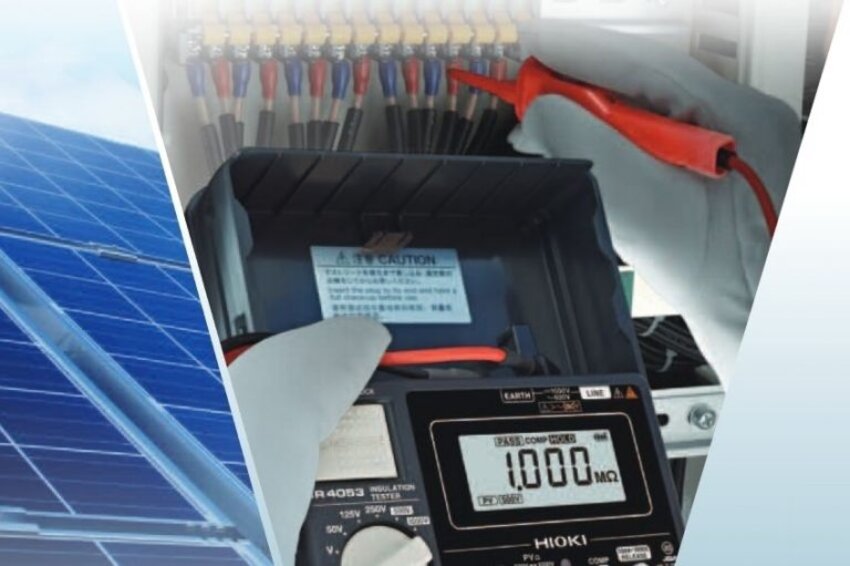
Testing the insulation resistance of the photovoltaic array
This is perhaps the most delicate test of all. It is necessary to use a megohmmeter, an instrument that applies a very high voltage between two points and measures the electrical resistance (mega-ohms) between them. Some more sophisticated multimeters already incorporate the megohmmeter function. The megohmmeter can also be an independent piece of equipment. There are two insulation test methods:
- Method 1: test between the negative of the photovoltaic string and the ground, followed by the test between the positive and the ground;
- Method 2: test between earth and the short circuit point between positive and negative. In other words, the insulation resistance of the positive and negative poles in relation to earth is simultaneously tested, when they are connected to each other.
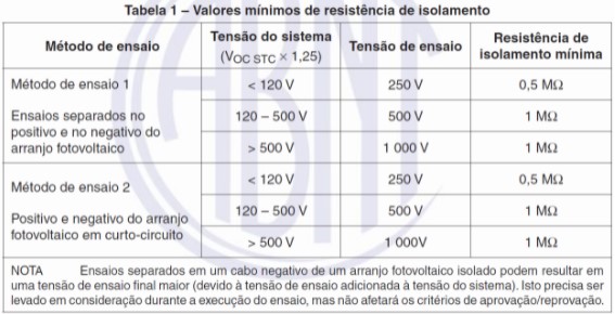
Table 1 of NBR 16274 shows the necessary test voltage values (voltage that the instrument must apply) according to the voltage levels found in the photovoltaic installation. In the last line we see that a test voltage of 1000 V is necessary in the most extreme case. It is then recommended to purchase a megohmmeter capable of providing at least this voltage value.
Instrument summary
See how easy it is? You only need a multimeter and a megger to commission a photovoltaic system. It may also be useful to have a clamp meter (for direct current) and a solar radiation meter. I would even say that the multimeter with pliers is the main instrument you need to have, in addition to the megohmmeter.
DC voltmeter (multimeter)
Used in polarity test, stringbox test and open circuit voltage test. Example:
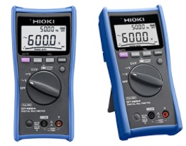
Multimeter with pliers
Common multimeters are generally not good for measuring direct current – the maximum ranges are generally 10 A. For this reason, the clamp-on multimeter becomes the most interesting instrument for the photovoltaic commissioning professional's toolbox. In addition to having the function of a voltmeter, the clamp multimeter allows you to measure currents well above 10 A.
Attention: you need pliers capable of measuring DC current. Not all pliers have this function. The clamp meter is used in operating current testing or short circuit current testing. Attention: if you are going to do the short circuit test, don't forget to have a DC sectional switch on hand (the same one used in stringboxes). Examples:
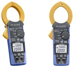
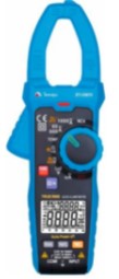
Note: the 3367C multimeter allows you to commission systems up to 1000 VDC only, while the CM4374 allows you to commission all photovoltaic systems up to 1500 VDC (which is the maximum voltage value allowed in photovoltaic installations).
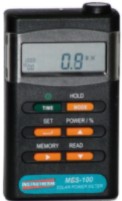
Solar Radiation Meter
It may be useful to monitor short-circuit current tests if atmospheric conditions are unstable. If you are in Pernambuco, in the midday sun, without clouds, this instrument is unnecessary. Example:
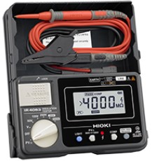
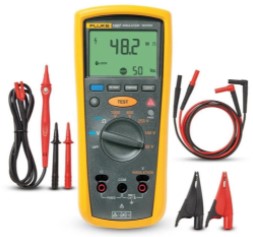
Insulation Resistance Meter
Examples:


One Response
Hello, good afternoon, regarding the article above “Basic equipment for commissioning PV systems”, how do I charge for the service? I have a 333 KWp plant to commission and I don't know how much to charge for the service.
Thanks.