
The design of a photovoltaic project assumes a long operating life of its components, with little need for replacement and maintenance.
All materials exposed to the weather suffer more accelerated degradation due to variations in temperature, humidity, solar radiation and mechanical stress caused by wind, for example.
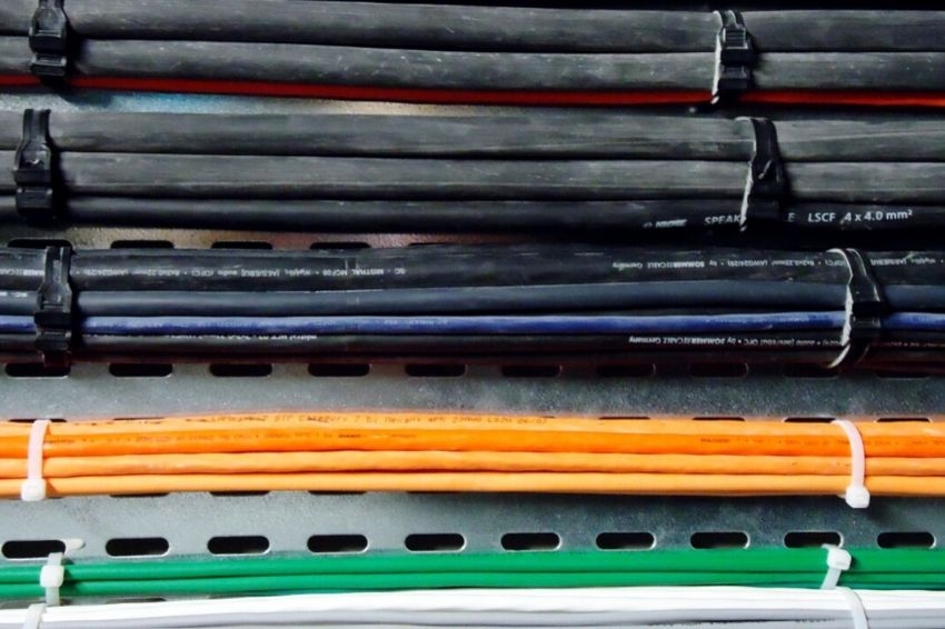
Cables are especially susceptible to this aging, as in addition to the influence of bad weather, they are heated by the passage of electric current and mechanical stress by wind or daily movement in solar plants with trackers.
The cabling used in photovoltaic systems must be robust and safe, mainly.
They must be compatible with the voltage levels and thermal and mechanical stresses over the assumed 25 years of operation of the plant. In this article, we will address the electrical and mechanical standards and definitions that must be met by cables used in photovoltaic circuits.
Characteristics of photovoltaic cables
The cables most easily found on the market today have 3 main types of insulation: PVC, EPR and XLPE, with specific standards describing their characteristics for each operating voltage range.
The insulating material and covering directly influence a cable's ability to work under heat, its insulation resistance and other mechanical characteristics such as elasticity, durability and protection against ultraviolet (UV) radiation.

The characteristic of these cables aims to guarantee long-term safety, by preventing melting or peeling of the covering and insulation, which could eventually cause an electrical arc, the main source of fire in photovoltaic systems. This subject was addressed in the articles Fire in PV systems: the dangers of electric arc It is What are the real fire risks in PV systems?.

Understanding circuit sections
The standards that govern photovoltaic systems, such as NBR 16690 (Electrical installations of photovoltaic arrays – Project requirements) and the NBR 16612 (Power cables for photovoltaic systems, non-halogenated, insulated, with cover – Performance requirements), specify the mechanical and electrical characteristics of the cables used in each section of an installation. The figure below illustrates the nomenclature of these sections.


All cables in the direct current circuits that make up a photovoltaic system must comply with the following specifications described in the NBR 16690 standard:
- Be suitable for direct current;
- Have an insulation voltage greater than or equal to the application voltage of that circuit;
- If exposed to the weather, protection against UV radiation;
- Non-flame propagating;
- Have double insulation;
- If exposed to a saline environment, they must be made of tinned copper.
In addition, all drivers must also follow the NBR 16612 standard, which contains more demanding requirements:

- Does not allow halogenated insulation and coverage;
- Insulation and covering must be made of thermosetting material;
- Minimum insulation voltage of 1.5 kVdc and maximum of 1.8 kVdc (equivalent to 0.6/1 kVac);
- permanent conductor temperature of up to 90 °C, allowing operation at 120 °C as long as 20,000 hours of use at ambient temperatures of up to 90 °C are not exceeded;
- Tinned copper conductor;
- Have identification “USE IN PHOTOVOLTAIC SYSTEM” and “NBR 16612”;
- Be soft-tempered, that is, flexible;
- Meet special construction requirements such as layer thickness and mechanical, thermal and aging resistance criteria.
The NBR 16690 standard allows the use of cables other than “solar cables”, as long as they are not exposed to UV radiation and do not form photovoltaic series. However, these cables must – in addition to following the basic requirements described in NBR 16690 – also follow the minimum requirements described in NBR 16612. The excerpt from the NBR 16690 standard below says that the cable specification for sub-arrays and arrangements must also meet the requirements of standard NBR 16612:

The cables can be constructed in accordance with standards NBR 7286 (EPR cables with insulation between 1 kV and 35 kV) or NBR 7287 (XLPE cables with insulation between 1 kV and 35 kV). It is worth remembering that there are also EPR and XLPE cables with insulation below 1 kV, which follow another standard and cannot be used in photovoltaic systems.
The EPR or XLPE cables specified above cannot be used in sections where the use of NBR 16612 solar cables is mandatory nor in sections that form photovoltaic series or are exposed to UV radiation.
These are not required to be tin-plated, and may even be made of aluminum and, although the steady-state temperature criterion is greater than or equal to the 90 °C required for solar cables, the overcurrent operating temperature criterion is not, making them incompatible for the formation of photovoltaic series (strings).
Cables with PVC insulation or covering, even if of a compatible insulation class, cannot be used in any section of the DC circuit of a photovoltaic installation, as they contain halogens in their formulation, which when ignited release toxic gases, in addition to not complying with to the temperature criteria set out in standards NBR 16612, 7286 and 7287.
EPR and XLPE cables that follow the NBR 7286 or 7287 standard are non-halogen, that is, their smoke is non-toxic, in addition to being thermosetting compounds, which do not soften or harden with temperature variation.
It is worth remembering that, as the minimum requirements of the NBR 16612 standard are more demanding than those of the NBR 7286 and 7287 standards, not all EPR/XLPE cables of 1 kV or more can be used. EPR / XLPE cables that simultaneously meet the NBR 7286 and NBR 7287 standards and the requirements of NBR 16612 and 16690 are not so easy to find. The table below highlights the electrical and mechanical characteristics of each cable:
Table: Characteristics of the cables described in their respective standards

Current carrying capacity
As we can have more than one type of DC cabling installation, it is necessary to pay attention to the current carrying capacity of each line in the installation. NBR 16690 specifies for each of the circuit sections which standard must be met in reference to current conduction capacity and correction factors.
Fragment of the NBR 1660 standard:

Table 5 of the NBR 16690 standard lists the existence of an overcurrent protection device and the current carrying capacity of the cables:

According to the NBR 16690 standard, in the sub-array and arrangement sections, as long as they are not exposed to UV radiation or close to the modules, we must adopt the current carrying capacity tables, installation method and correction factors of the NBR standard 5410. In sections where photovoltaic series are formed, we must use the current carrying capacity table and its respective corrections and installation methods from the NBR 16612 solar cable standard.


One Response
Is the electrical resistance of these cables greater than that of common cables?