The definition of the photovoltaic inverter is an essential step in any project, whether distributed generation or centralized generation.
Choosing equipment with the appropriate characteristics for a given application allows you to maximize energy generation and return on investment, as well as reduce the project's levelized cost of energy (LCOE).
In this process, technical parameters must be considered such as maximum output power, voltage levels, equipment overload, number of inputs and MPPTs, application location (proximity to the sea, ease of access, string orientation, etc.), among others.
More subjective aspects must also be compared and analyzed: how is the inverter manufacturer seen by the market? What after-sales services are provided? How to claim the warranty? Parts replacement time?
Therefore, it is important to know the operating history and past projects with this equipment.
The objective of this article is to describe a real application, in Brazil, using inverters as components Solis-(215-255)k-EHV-5G. The plant's operation and performance are analyzed using the SolisCloud monitoring platform.
Description of the plants
The project chosen for analysis is located in the state of Minas Gerais, approximately 70 km from Belo Horizonte. The energy produced is fully injected into the concessionaire's network and sold to a consortium of companies.
This project is divided between two plants totaling 2.5 MW. The oldest plant (Plant 1) is made up of eight inverters Solis-125k-EHV-5G, totaling 1 MW and operating for just over two years. The second plant (Plant 2) was installed in 2022 and operates with six inverters Solis-250k-EHV-5G.
The main characteristics of the inverter models used are shown in Figures 1 and 2 below.


The model Solis-125k-EHV-5G It has a single MPPT with 20 parallel inputs. Already the Solis-250k-EHV-5G It is one of the highest power string inverters currently available, with 14 MPPTs and 28 inputs – Figure 3.
With one high overload ratio It is intelligent heat dissipation design, the inverter adapts to extreme environments without compromising its generation.
This inverter matches perfectly with high power modules to help the system owner achieve a lower LCOE. Optimal fit between inverter and high power modules can result in up to 7% reduction in LCOE.
It is noted that the two inverter models adopted work with photovoltaic strings of up to 1500V. This allows longer strings to be constructed and a reduction in the number of strings in parallel.
As a result, it is possible to reduce electrical losses, in addition to reducing the cost of cabling, connectors and protective equipment when compared to a system with a lower maximum voltage.


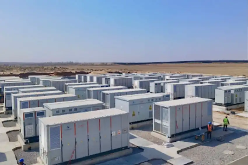
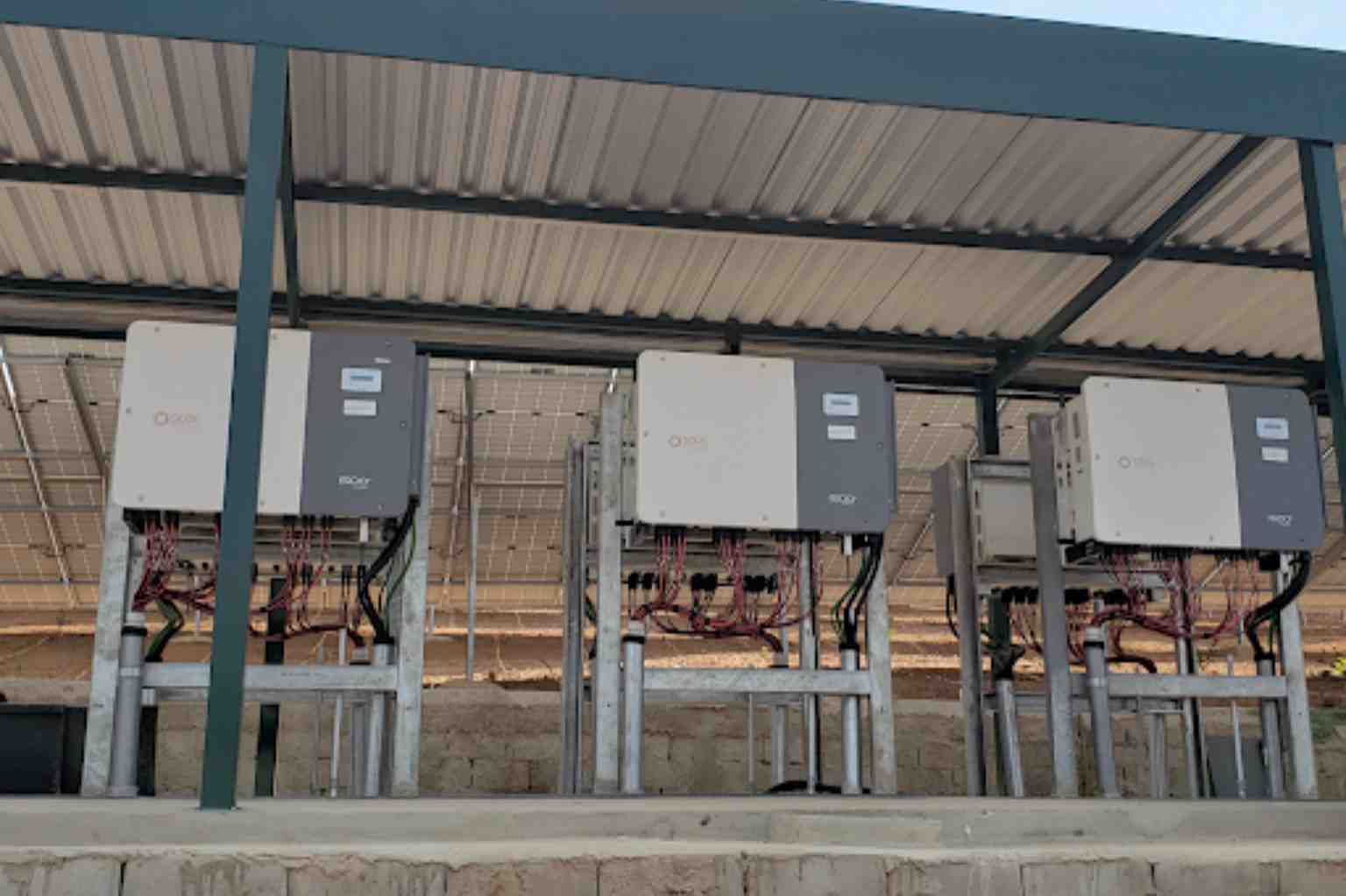
In relation to the topology of the two plants, a centralized design was chosen – Figure 4. Thus, a shelter was built for the installation of the inverters, along with BT, MV panels and transformers.
To connect Plant 1 and Plant 2 to the concessionaire's MV network, 13.8 kV, 1.25 MW and 2 MW transformers were used, respectively. The energy delivery point is located 50 meters from the Cemig substation with overhead cables to Plant 1 and underground cables to Plant 2.

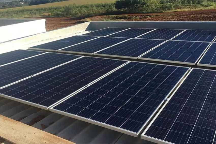
For Plant 1, 3,136 390 W modules were installed, resulting in inverters with 22% of overload. Each inverter at Plant 1 is connected with 14 strings, each string having 28 modules.
For Plant 2, 3,696 550 W modules were used. At Plant 2, each inverter works with 22 strings and 28 modules per string and, therefore, with an overhead of 35%.
As all Solis inverters have integrated protections, in accordance with international and national standards, a design was chosen no stringbox.
The strings are connected directly to the inverters. Furthermore, no tracker is used to move the photovoltaic strings.


The table below shows a summary of the main information for Plant 1 and Plant 2.
| Plant 1 | Plant 2 | |
| Inverter | 8 x Solis-125k-EHV-5G | 6 x Solis-250k-EHV-5G |
| Qnt. of Modules | 3136 (390W) | 3696 (550W) |
| Inverter overload | 22% | 35% |
| Average energy generation (MWh/month) | 170 | 270 |
Performance
To analyze the operation and performance of the plants, the information provided by the Solis monitoring system is used.
O SolisCloud is the newest management system for Solis inverters. Through a modern interface, the platform provides information about the plant's performance, profitability and O&M.
The collection of technical and performance data from the plants is carried out through fiber optic cables and also using the Solis datalogger. All information is compiled and transmitted by the inverters with a sampling rate of 5 minutes.
The average combined power output of Plant 1 and Plant 2 is about 440 MWh/month. Considering only inverters 250 kW are produced on average 270 MWh/month. These values vary depending on the seasons and daily fluctuations in temperature and irradiation.
For a more detailed analysis of energy generation, an inverter was chosen Solis-250k-EHV-5G of Plant 2. Figure 5 displays the daily inverter generation of 250 kW for the month of July 2022.

It is possible to verify that the inverter worked throughout the month, with an average daily generation of 1.37 MWh. The generation peak occurred on 07/12. That day, the inverter worked for 7 hours and produced around 1.75 MWh.
The plants were very cloudy on the 3rd and 6th of the same month, where the inverter had a lower production and close to 550 kWh per day, a value almost 3 times lower than the maximum for the month.
Considering only this inverter, total production in July exceeded 42 MWh. These values are within expectations for the time of year and local temperature and irradiance conditions.
Figure 6 below shows the inverter behavior for the highest generation day of the month. The curve produced during the daily generation of the equipment is that expected from a photovoltaic inverter on a sunny day with little cloud cover.

The generation curve shows that the inverter started processing energy at dawn, around 6:20 am. Generation grows throughout the morning and reaches its maximum around 11:55 am. At this time, the inverter output registered around 240 kW, that is, 96% of the equipment's maximum power.
Few fluctuations in energy production were observed that day. The main oscillations occurred around 11:20 am and 12:35 pm, and were probably caused by the rapid passage of clouds. Inverter generation was terminated at 5:55 pm, when local irradiation reached the minimum value to keep the equipment functioning.
Another point of analysis using the platform SolisCloud are the technical parameters of the inverter. In Figure 7, the voltages in all 22 strings used in the inverter for the same day were plotted.

As mentioned previously, the inverter started operating at 6:20 am. Figure 7 makes it clear that at the same time there were already strings with voltage levels above 1000 V. This value was more than enough to start the equipment, which has a starting voltage of 500 V.
Likewise, it can be seen that around 6pm the voltages of all strings dropped below 500 V, causing the equipment to shut down. Thus, as the voltage information was viewed, technical parameters such as current, power and temperature can be selected on the platform.
Figure 8 below shows the temperature evolution of the equipment throughout the day. This temperature is measured in the IGBT, the internal component for which the inverter is responsible for converting between direct and alternating current.

Reaching a maximum temperature of 75.2 ºC, the inverter shows an excellent heat dissipation design. Even with 240 kW output, the inverter operates with a sufficient temperature margin and without compromising its performance and useful life.
In conclusion, the data collected by monitoring and field visits for maintenance show a satisfactory performance of Plant 1 and Plant 2.
The installed 125 kW and 250 kW inverters are operating and producing energy as expected, with Plant 1 having been in operation for over 2 years and Plant 2 having been in operation for around 6 months.
It was seen that even operating close to its maximum output power, the 250 kW inverter maintains its operating temperature relatively low without compromising its performance.