After the introduction of the photovoltaic system, the installation's power factor is reduced with the injection of active power from the solar panels.
Power factor correction can be performed by the photovoltaic inverter itself or by capacitor banks.
In addition to power factor correction, the power control feature (active or reactive) of inverters can be used to support voltage control in long distribution networks or autonomous networks.
The power factor of electrical installations
Electricity consumers are divided into ranges according to their supply voltage, according to the tables below.

In conventional electrical installations (without the presence of photovoltaic systems) the power factor has always been a cause for concern. The causes of low power factor are high-power induction motors operating at no load (as is common in machine tools), empty or under-loaded transformers, fluorescent lamps and the presence of many low-power motors (in refrigerators and appliances). air conditioning, for example), among other things.
The power factor can also be reduced by the presence of many non-linear equipment such as welding machines, electronic lamps and circuits with rectified input in general.
REN 414 (Normative Resolution No. 414/2010) and REN 569 (Normative Resolution No. 569/2013) from ANEEL (National Electric Energy Agency) regulate the definition, reference values and scope of application of the power factor for billing surplus reactives from consumer units.
According to these resolutions, Group B consumer units cannot be charged for excess reactives due to the low power factor. For Group A consumer units, the power factor, for billing purposes, must be verified by the distributor through permanent measurement.
The power factor of these consumers has a minimum limit of 0.92. If the consumer has a power factor below this value, a fine for excessive use of reactive energy will be charged. Power factor control in conventional installations, in Group A consumers, is carried out through capacitor banks associated with supervision and control systems.
A power meter monitors active power and reactive power consumption. As necessary, depending on the loads used in the installation (motors and other equipment), a greater or lesser number of capacitors are added to the installation.
This is a technologically simple solution and is widely used in all types of commercial or industrial consumers who have problems with the power factor and have a lot of intermittency in their demand curve (that is, they have machines that go in and out of operation all the time ).

Power factor x photovoltaic systems
Inverters grid tie They inject active energy produced by photovoltaic modules into the electrical installation. The injection of active power worsens the power factor of the installations, as from the distributor's point of view the consumer starts to use less active energy from the electrical grid, which increases their reactive energy consumption proportionally.
Despite not causing any change in reactive energy consumption, photovoltaic systems cause a reduction in the power factor in Group A consumers.

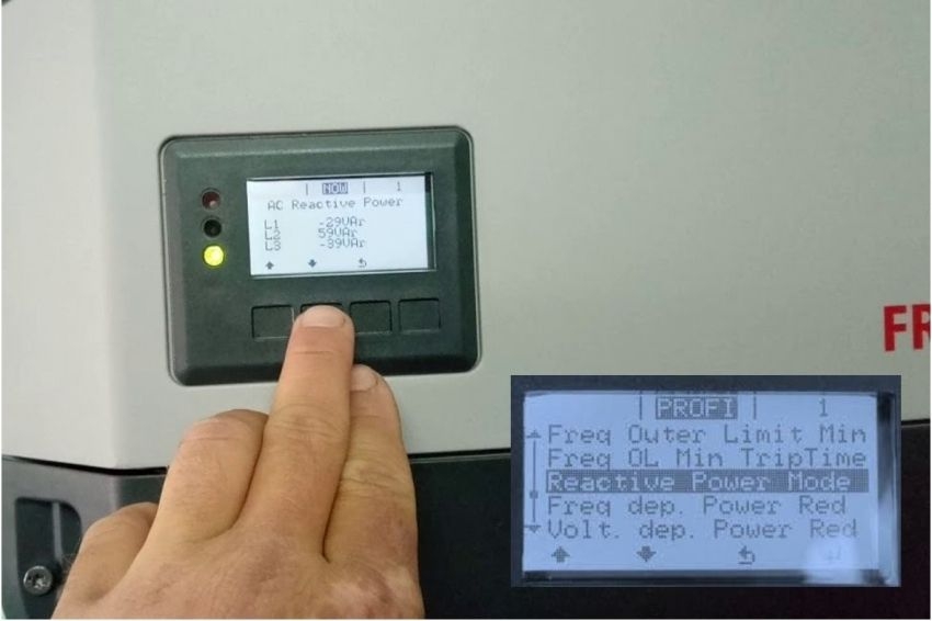
Reactive power control through inverters
The inverters grid tie for photovoltaic systems it has the ability to inject reactive power. In this way, they function as electronic capacitors or inductors. By controlling the phase shift of the electric current, the inverter is capable of producing inductive or capacitive currents.
The secret to the ability to control reactive power is the inverter's output current control system. This system makes the inverter behave like a controlled current source. We can ask the inverter to generate any type of current, of any amplitude, frequency or phase.
The output current of the photovoltaic inverter is always sinusoidal and synchronized in frequency with the electrical grid voltage. Depending on the amount of active or reactive power that is desired at the inverter output, the amplitude or phase of the current can be changed by the software inverter control.
Although it is possible to correct the power factor of the installations with the injection of reactive power by the inverter, three main facts must be remembered:
- The inverter's power factor injection feature is not intended to replace capacitor banks, but only to provide adjustments to the reactive supply to improve power factor or support voltage and frequency control on weak electrical grids. which can be end-of-line distribution networks, with high impedance, or autonomous networks (micro-grids);

- Using the inverter's reactive power injection capability reduces its ability to inject active power. Inverters used for this function must generally be oversized.;
- The inverter only provides a small portion of reactive power, defined by a capacity curve. This means that in the absence of active power, the inverter does not have the capacity to inject reactive power. It is not possible, for example, to perform nighttime power factor compensation with an inverter grid tie.

If the inverter is programmed to generate only active power, the output current is always synchronized in phase with the voltage. If we want the inverter to produce reactive power, the phase between current and voltage will be changed according to the type of injection and according to an algorithm pre-programmed in the inverter.


Inverter power control modes
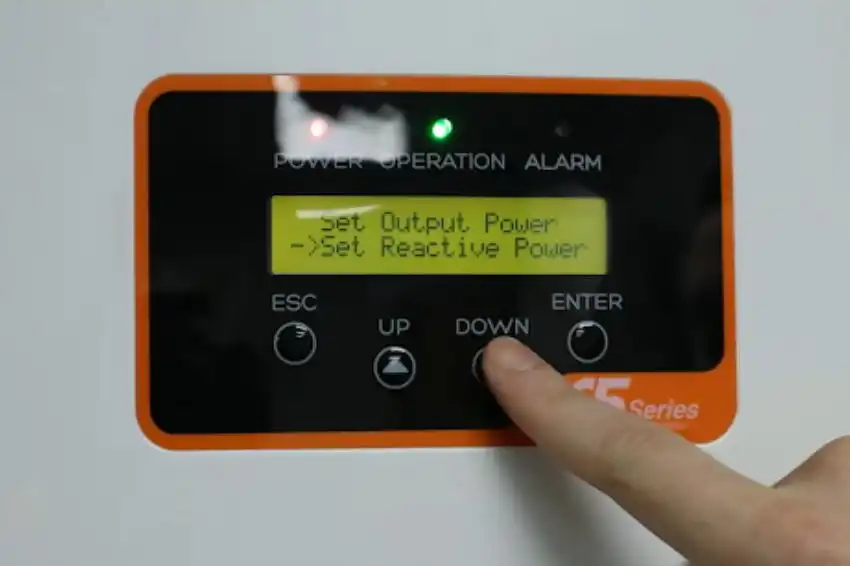
Most inverters grid tie It has pre-programmed reactive power control modes. The different modes can be used according to the objective to be achieved with the injection of reactive power or the limitation of active power in the installation.
What all modes have in common is the control of the portions of active and reactive power injected by the inverter into the electrical grid. What changes from one mode to the other is the size of each installment and the way they are adjusted.
Active power limitation
In this mode, the inverter limits the power extracted from the modules by reducing its input voltage. Reducing active power is one of the ways to control the value of an installation's power factor, preventing excessive injection of active energy. This way, the inverter's output power can be adjusted to a percentage value of the power consumed in the installation.

In reality, this control mode is very useful in situations where you want to avoid the export of active power to the electrical grid, ensuring that the inverter will only inject the energy necessary to be consumed locally.
Furthermore, this control mode can be useful for autonomous networks that have another power source in parallel – such as a diesel generator, for example. By limiting the inverter's power, it is possible to prevent the diesel generator from receiving excess energy from the system when solar generation is very large, but there is no consumption.
P xf control – active power limitation
Controlling active power as a function of frequency is useful for controlling the frequency of autonomous electrical networks. Although this control mode is not necessarily associated with the need to control the power factor of the installations, it is interesting to include it here.
The following figure shows an active power curve (P) as a function of network frequency (f). In photovoltaic systems connected to the distribution network, frequency is not a variable that can be changed. In autonomous networks, however, the bus frequency may increase if there is excess active power. This frequency increase can be contained by limiting the inverter output power.

P x U control – active power limitation
The control of active power as a function of voltage is similar to the previous mode, however the reference variable is the bus voltage and not the frequency.

Reactive power control
The following figure illustrates the situation in which the inverter simultaneously supplies active and reactive power to the electrical grid. The quantities of P and Q can be controlled according to the installation’s needs.
The values of P and Q can be determined by a supervisory and control system external to the inverter. The amount of reactive power injected by the inverter must respect its capacity curve.





7 Responses
Goodnight?
I have a big question: Because the power of the solar panel is in WATTS. What is the Power Factor considered on the board?
Good afternoon Paulo, how are you? The solar module works on direct current and has no power factor
Good evening everyone!
I assembled a 4.20 KWP system, it is ready and needs inspection. The dealership is asking me for this below, I can't even imagine what it could be, can anyone help me?
Adjustment of voltage, frequency and power factor parameters according to the “Inspection through Photographic Report” file (see the “Photovoltaic Project” tab).
Hello Thiago, good evening! I saw your comment and am interested, please contact me (86) 99822-6973.
Hello Marcelo Villalca, I have a problem with a low power factor due to the installation of a Photovoltaic Plant, I made the necessary calculations and installed Capacitors to correct it, but throughout the day and depending on the solar incidence, it happens that the factor power hour is correct and hour is low.
I would like to know if it is necessary to carry out an automated installation of this Capacitor Bank for perfect operation, as this is the first time I have come across this situation and I have doubts.
Thank you very much in advance!
Good evening Gilberto, we are specialists in automatic capacitor banks, really with the advent of photovoltaic systems capacitor banks must be modified, send us a request so we can talk about it, 67 3221 7847
Hello Gilberto, in this case it is ideal to use an Automated Capacitor Bank, because as solar generation varies its active power according to the day's irradiation, shading and the like, the fixed capacitor bank does not follow this variation in active power, maintaining its fickle power factor.