
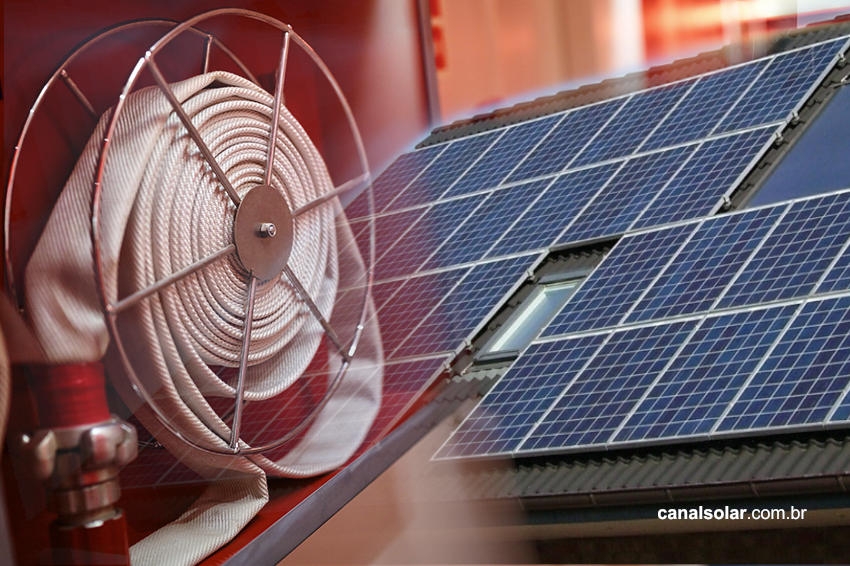
Photovoltaic installations, like any electrical installation, are subject to equipment and installation failures that can cause fires.
However, given its relatively new introduction into the market, the reasons for equipment, design and installation failures that can lead to accidents are not yet fully understood either by the end customer or by most professionals in the sector.
It is recognized that the main point of failure in photovoltaic systems is poor quality connections of the direct current part of the system [1], and that these are caused by electric arcs.
However, failures in other components of the installation still represent around 20% of the causes that lead to fire [2].
To fully understand the risks, a complete system analysis is necessary, which will be the topic of this article.
One point that should be noted is that photovoltaic solar systems are safe when designed and executed by trained professionals.
Overview of photovoltaic systems
Germany was the first country to develop a large number of photovoltaic systems, thus having a good percentage of systems with ten years or more of installation. Therefore, there is a wealth of data on the medium and long-term behavior of failures in PV systems.
Studies of fires in installations where there were photovoltaic systems [1] show that 56% of fire cases occurred due to lightning strikes and, of the remaining 44%, 17% of fires were caused by product failure, 9% by design errors and 18% by failures. installation.
Compared to the total number of photovoltaic installations in Germany (1.3 million) only 0.016% of installations suffered failures that led to fires. The annual number of fires of electrical origin in the country [3] is 18 thousand cases, far below the number of fires due to the photovoltaic system.

Of the internal failures, that is, the failures that were not caused by external events such as lightning, we have the following breakdown of the distribution of failures: 51% caused by installation errors, 19% caused by errors in the DC circuit, 12% by internal module failures, 10% for faults internal to the inverter and 8% for faults in the AC circuit.

Failure analysis
The electrical arc is the main component failure mechanism that causes fires in systems [1]. The sources of failure are detailed in the tables below according to the probability of occurrence.
It is noted that failures are mostly dependent on the quality of the installation.
Table 1: Faults causing electric arcs, ordered by probability of occurrence


DC Connectors
Electrical arcs in connectors are mainly caused by installation faults. To ensure correct fitting, it is necessary to follow the recommendations for the maximum size of the bare wire that fits into the terminal and also the correct use of a tool to terminate the conductor.
The use of incorrect termination pliers is the main cause of this type of connection failure [2]. The figure below illustrates the difference in termination quality for two types of pliers.

It is also common to find errors in the plastic cover that tightens the rubber seal. This type of error causes the ingress of water and pollutants, causing the connection to deteriorate, heat up and lose protection against electrical arcs.


Connectors from different models and manufacturers should also not be used in the same connection, as perfect electrical fit and insulation of the male-female pair cannot be guaranteed.
The standards for Brazilian and international photovoltaic installations themselves (NBR 16690 and IEC/TS 62548) clearly mention this issue.
Each manufacturer uses a different material, which can cause chemical incompatibility (contact corrosion) and mechanical incompatibility (different designs and thermal expansion), for example.
The use of different connectors can increase contact resistance, which in turn increases the internal temperature of the connector, which can reduce its useful life or even cause it to melt.


Excessive or insufficient application of torque to the termination of the MC4 connector or to the device screws can also cause high contact resistance or connection failures, as already discussed in the article on electrical arcs that we published here on Canal Solar.
Photovoltaic modules
The main fire mechanisms in photovoltaic modules are related to reverse current, module quality and the presence of microcracks.
The reverse current, already covered in our article “Causes and effects of reverse current in photovoltaic modules” is a failure situation where series in parallel have different Voc (open circuit) voltages, either due to an internal module failure (internal short circuit) or due to a design and installation error.
When the condition for harmful reverse current arises (two or more series in parallel with a series of distinct Voc), if the system is not protected by a fuse, the module will heat up, which now behaves like a reverse biased diode and may become a fire source.

The low quality of the modules can also cause accidents. Problems such as poorly done soldering, poor and poorly designed packaging, lack of care during transportation and installation can cause the module's internal conductors to weaken or break. When this occurs, an internal electrical arc and, eventually, a fire may also occur.

Microcracks caused by impacts or stepping on the modules, in addition to reducing the module's power, also pose a risk, since their cracks contain high electrical resistance that also causes heating. The figure below illustrates the increase in temperature caused by microcracks.

string box
Special care must be taken in the string box. Failure to apply the correct torque to the screws, the use of incorrect connections and box sealing problems are directly associated with the risk of electrical arcs and internal short circuits.
As for the components, it is essential that they respect the temperature, voltage, insulation and current limits for which they were designed. The technical specification of each of the string box components can be found in the article Understand the basic specifications of the String Box components.
It is mandatory that all external string boxes have a protection level of at least IP55. In a recent article, DPS: The airbag of photovoltaic systems, it becomes clear how the lack of internal quality of a component that was apparently correctly sized can cause a serious electrical failure.
Table 2: IP classification of protection against the ingress of solid and liquid bodies


Inverter and AC Installation
The inverter itself, especially when from a good quality manufacturer, presents little risk of internal arcing, precisely because it has a robust design and internal protections that can detect faults early.
Electrical defects in inverters are mostly due to [1] design and installation: terminals that are poorly crimped or have the wrong conductors and voltage and current limits that are higher than permitted.
The conditions of the installation location must also be observed: the NBR 5410 standard classifies environments and buildings according to their risk of combustion and gives guidelines on the level of protection of devices and conductors that can be used.
The sizing of AC and DC cables, according to current-carrying capacity criteria, is also directly related to the risk of heating and melting. For more information on sizing, read the article Sizing of cables and protections in photovoltaic systems.

Fault and fire prevention
Based on the fire studies shown previously, we can classify the main actions for preventing failures between design actions, installation actions and component selection actions.
Table 3: Actions to prevent failures and fires in photovoltaic systems

The Brazilian standard ABNT NBR 16274 dictates which commissioning tests must be carried out at the end of the installation, thus complementing fire prevention. This standard will be the subject of a future article here at Canal Solar.
Conclusion
Installing a photovoltaic system does not increase the risk of fire in an establishment. In a more mature market, such as Germany, only 0.016% of electrical fires were due to photovoltaic system failures.
Due to the growth of the solar energy market and the increase in the presence of new designers and installers, the technical training of professionals and the choice of good components are essential for fire prevention and the maturation of the national photovoltaic market.
A good choice of equipment is not limited only to its performance. When choosing equipment, it is important to consider the manufacturer's presence in the national market.
As the majority of failures are due to installation problems, good technical support and the provision of training by these manufacturers strengthen and mature the installations of market professionals.
References
- [1] Sepanski et. al., 2015. Assessing Fire Risks in Photovoltaic Systems and Developing Safety Concepts for Risk Minimization
- [2] PV bankability analysis, Stäubli
- [3] Consumer fire safety: European statistics and potential fire safety measures
- [4] World Fire Statistics 2018, International Association of Fire and Rescue Services


2 Responses
Congratulations on the article!
What suggestion would you give to prevent damage or electrical faults in the system and panels? In this case, those subject to the need for repair activities on the support supports of photovoltaic panels. If they require the electric welding process on the structure using a coated electrode. Logically, previously preserving the mechanical integrity of the panels and other components of the photovoltaic system? Thanks! Orlando Moreira.
Hello, Orlando, how are you? One of the essential practices for the proper functioning of the PV system is cleaning the modules, so that there is no obstruction in the “path” between solar rays and the module cells, and carrying out commissioning tests (carried out by trained professionals) to check connections and protections, and also to check the energy generation produced