The problem of partial shading in photovoltaic modules, in addition to causing loss of generation, is often responsible for the appearance of hotspots (heating points) in photovoltaic cells, as illustrated in Figure 1.
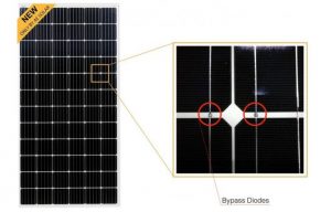
To avoid the hotspot effect, manufacturers add bypass diodes in parallel with a set of photovoltaic cells. In most commercially available modules there are three bypass diodes.
Typically the shadows cover a certain number of cells in the photovoltaic module.
However, in extreme situations it is possible for localized shadows to occur in a small number of cells – in the worst case, in just one cell – which can prevent the bypass diode from functioning, leading to the occurrence of the hotspot.
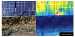
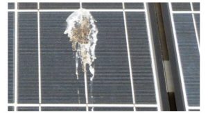
Localized shadows can be caused by obstacles such as chimneys, poles, power distribution cables or bird litter, as illustrated in Figure 2.
Total hotspot prevention can be accomplished by adding a bypass diode to each cell of the PV module.
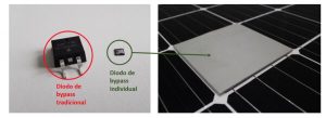
Although most manufacturers prefer the collective bypass diode solution (for a group of photovoltaic cells), the individual bypass diode solution (as illustrated in Figures 3 and 4) already exists commercially, having been introduced exclusively to the market. by AE Solar, a photovoltaic module manufacturer based in Germany.
Experimental study
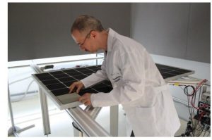
A study conducted by the Fraunhofer Institute (Germany) with modules from AE Solar, validated the individual diode solution based on an experiment with two photovoltaic modules, one traditional (with a collective diode) and the other with a dedicated diode, of the hotspot-free type.
Know more: AE Solar develops hot-spot-free and shading-resistant module
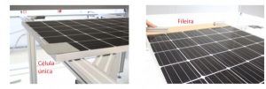
The experiment was carried out by applying partial shadows to the modules through the addition of opaque screens over cells or groups of cells, as shown in Figure 5.
In the experiment, three conditions were used, applied to the two types of modules analyzed:
- Test condition 1: Shadowing of only one cell;
- Test condition 2: Shading of a row of cells;
- Test Condition 3: Shadowing of multiple rows of cells.
A row of cells is defined as a group of cells aligned horizontally (considering the module in portrait position), but not belonging to the same string, as shown in Figure 6.
Study results
The results of the experimental study carried out are shown below. The results show the influence of the effect of bypass diodes on the power generated by the photovoltaic module.
Although the main function of the bypass diode is protection against the occurrence of the hotspot, there is a (desirable) side effect of the diode on the performance of the photovoltaic module.
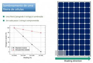
In the traditional module, the activation of a bypass diode causes the loss of a complete string of cells. In the hotspot-free module, on the other hand, the loss is gradual, proportional to the number of shaded cells, as shown in Figure 7.

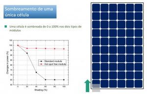
The graph in Figure 7 shows that shading just 60% from a cell causes the loss of 1/3 of the output power of the conventional photovoltaic module. This is explained by the removal of an entire string (20 cells) when one of the bypass diodes is activated.
On the other hand, as shown in Figure 7, in the AE Solar hotspot-free module, the power remains at around 97% in the same test condition.
An interesting fact that can be observed in Figure 6 is that there is an almost linear relationship between the percentage of shading and the power reduction of the hotspot-free module.
In the case shown, only 1 cell (among the 60) of the photovoltaic module is shaded, which would correspond to a shading of 98.3% – considering only the active area of the module, that is, the area corresponding to the surface of the photovoltaic cells.
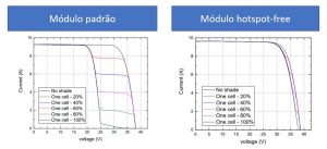
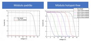
The results in Figure 7 are explained based on the IV curves of the photovoltaic modules, shown in Figure 8, when subjected to the conditions described previously.
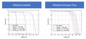
Figures 9 to 12 show the results obtained with the other test conditions, that is, with shading of 1 row and several rows of photovoltaic modules.
Analysis of results and conclusion
An experiment was carried out to evaluate the performance of an AE Solar hotspot-free photovoltaic module compared to a conventional module under partial shading conditions.
In the experiment conducted by the Fraunhofer Institute, tests were carried out with different shading conditions, according to three standards applied equally to the two types of modules evaluated: shading of just one cell, shading of a row and shading of several rows.
With the shading of just one cell, AE Solar's hotspot-free module showed losses of just 3%, while the conventional module lost 35% of power.
With the shading of a row, the standard module loses 100% of its power, having its three bypass diodes activated. Under the same condition, AE Solar's hotspot-free module loses only 20% of the total power.
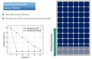
With multi-row shading, the power of AE Solar's hotspot-free module decreases linearly with the increase in the module's shaded area. On the other hand, the conventional module completely loses its power when it has 50% from the shaded rows.
It is important to highlight that the result obtained with the test in condition 3 is only valid when shading occurs from bottom to top. If the shadow advances in a horizontal direction (from right to left or vice versa) the power loss in the conventional module may be even greater.
This article focused on the problem of power loss with partial shadows. This problem can be alleviated by using a greater number of bypass diodes in the photovoltaic module – ideally, one diode for each cell, as is the case with AE Solar's hotspot-free modules.
References
Electrical Characterization of hotspot-free and standard module. Hamed Hanifi, Frank Wenger, Jens Schneider, Report No. 389/2018, Fraunhofer
https://hsfsolar.com/smart-hot-spot-free-modules/ – accessed on 07/28/2021
Aerial thermography of photovoltaic solar plants https://canalsolar.com.br/termografia-aerea-de-usinas-solares-fotovoltaicas/ – accessed on 07/28/2021


One Response
This means that the use of diode per cell is highly effective, high quality article of information, I hope the next article will be about the use of mppt per cell in panels, to solve shading, as they are already being applied by Jinko Solar.