When we analyze the data sheets of some solar inverters we see highlighted in their descriptions the number of inputs MPPT (from English Maximum Power Point Tracking, or Maximum Power Point Tracking in Portuguese) that the equipment has.
Furthermore, it is possible to find inverters with similar powers and characteristics, differing only by the number of MPPTs. This article aims to expose the characteristics and advantages of an inverter with multiple MPPTs.
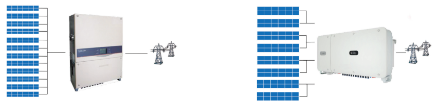
Generally speaking, an inverter with multiple MPPTs differs from conventional inverters by the way the solar modules are controlled. In conventional inverters (which only have 1 MPPT), the set of photovoltaic strings is treated as a single block.
All strings have their maximum power point tracked simultaneously by the only MPPT system available. Even though the inverter has several inputs for connecting different strings, inside the inverter all strings are controlled as a single block.
In inverters with several MPPT inputs the situation is different, as we can see in the figure below. The strings are divided into smaller blocks and each block is under the control of a distinct MPPT input. The latest inverters on the market typically have 2 to 4 MPPT inputs.
Power of photovoltaic arrays
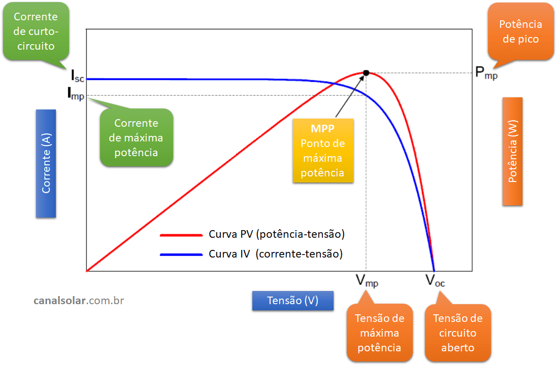
The power of an array of photovoltaic modules is defined by the product of the current and the array voltage at a given operating point. The relationship between the current and voltage of the modules is determined by the IV curve shown below. Understand what the IV curve is in the article Understanding the IV and PV curves of photovoltaic modules.
In the graph in Figure 2 we have:
- Bait – Short circuit current: this is the maximum electrical current that the module can provide.
- You – Open circuit voltage: this is the maximum voltage that the module can provide.
- imp – Maximum power current: this is the current that the module provides when operating at its maximum power point.
- Vmp – Maximum power voltage: this is the voltage that the module presents at its terminals when operating at its maximum power point.
- Pmp – Maximum power: this is the peak power of the photovoltaic module.
- MPP – It is the maximum power point of the photovoltaic module (maximum power point). It lies at the knee of the IV curve and the peak of the PV curve.
The association of modules in strings or arrangements also presents the same electrical characteristics mentioned above. What changes are the values. Voltage and current can vary due to several factors such as temperature, lighting, dirt or shadows on the modules and equipment degradation, causing a loss of power and displacement of the Imp and Vmp points.
As shown in Figure 2, it is noted that there is a point at which the use of the arrangement is maximum. To obtain the highest power from the arrangement, we must try to operate it close to its maximum power point – MPP. The electronics built into the inverters are capable of shifting the equipment's operating point (Imp, Vmp) to operate close to the MPP, causing adverse effects to be reduced and the power to be maximum for that situation.
This ability of the inverter to operate at the Imp and Vmp point and to be able to vary and search for these points, depending on external conditions, is called MPPT – Maximum Power Point Tracking.
Multiple MPPT inputs
It is common in photovoltaic projects to install more than one arrangement on the same inverter, using string boxes or direct connections to the equipment.
In traditional inverters (with only 1 MPPT input) the photovoltaic strings (modules connected in series) must have identical characteristics to be connected simultaneously to the inverter.
On the other hand, inverters with multiple MPPT inputs allow the connection of strings and arrangements with different characteristics. Each arrangement may have a characteristic that depends on its location, installation angle, shading, number of modules connected in series, among other things.
The inverter with more than one MPPT input is capable of simultaneously operating two or more arrays with different characteristics at their maximum power points.
In summary, an inverter with multiple MPPT inputs allows the connection of arrays with different powers and inclinations, in addition to being able to monitor each of the MPPT inputs separately.
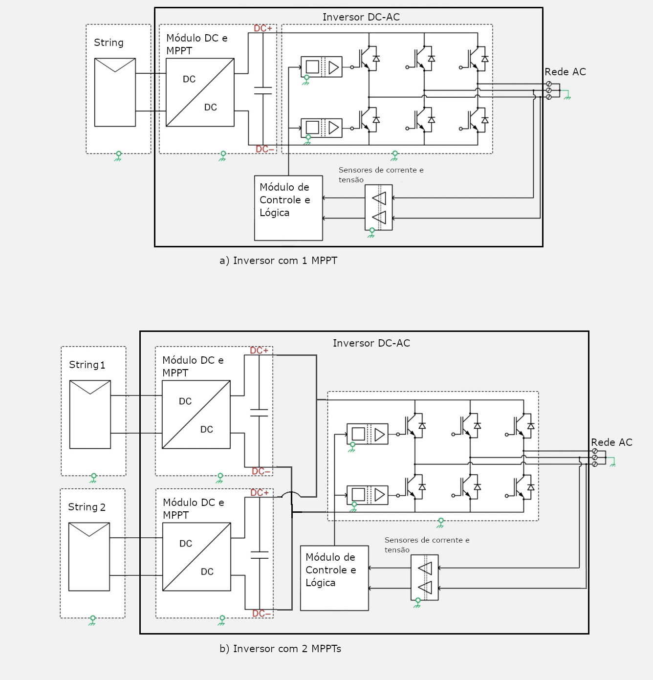
Below we see two diagrams showing the internal organization of a conventional inverter and an inverter with multiple inputs. The output, which corresponds to the DC-AC conversion stage, is identical in both. The difference occurs at the input, with a greater number of DC-DC modules (with the MPPT feature) in inverters with multiple inputs.

Application example
Arrangements with distinct characteristics
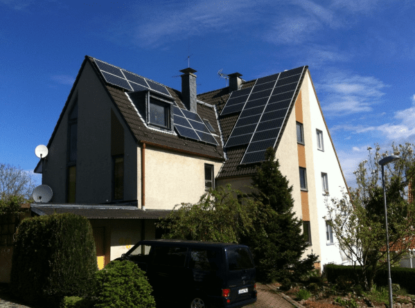
In the residential project in the figure below, it was necessary to install two arrangements with different orientations, one with 3 kWp on the north side of the roof and the other with 2.5 kWp on the east side. Therefore, we will have different energy generation conditions and different points of maximum power.
Panels on both sides of the roof cannot be connected to the same inverter input. The solution is to employ different inverters or an inverter that has two MPPT inputs.
If the modules of this system are connected to an inverter with only one MPPT, the equipment will operate seeking a point of maximum power for the entire set, but will not be able to seek the maximum power that each arrangement individually could generate, as they are arrangements with distinct generation characteristics.
For maximum system usage, the inverter must be replaced with a model with 2 MPPTs, with each arrangement connected to an MPPT. This way, the maximum power point will be reached for each of the arrangements independently.
Before the popularization of inverters with multiple MPPTs, this problem could only be solved by using two inverters, adding complexity and cost to the project. Inverters with multiple MPPTs provide a faster and cheaper solution, being able to work with arrays in different conditions using only a single inverter.
In addition to inefficiency, mixing arrangements with different electrical characteristics in the same MPPT is dangerous and can cause reverse current flow and eventually fires, as mentioned in the article Study of caso – Fire in photovoltaic solar inverter.
Arrangements with identical characteristics
Inverters with multiple MPTTs are also advantageous in uniform arrangements, that is, when all modules are installed in the same way and the strings are identical, having the same number of modules.
For example, a 100kWp plant with modules organized in identical 16.6kWp arrangements, connected to an inverter with 6 MPPTs, will have maximum power tracking for each set, in addition to enabling individual monitoring of the sets connected to each of the inputs. of MPPT.
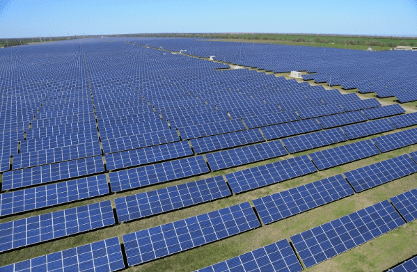
As the inverter can measure the power of each of the MPPTs, the detection of any failure is facilitated and its impact is minimized, as the other arrangements will continue to operate at their maximum power point.
Example of inverters with multiple MPPT inputs
Below we find the Sunny Boy 5.0 model from SMA. This 5kW inverter has 2 MPPT inputs and allows you to connect two strings per MPPT, totaling 4 strings.
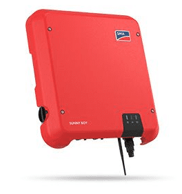
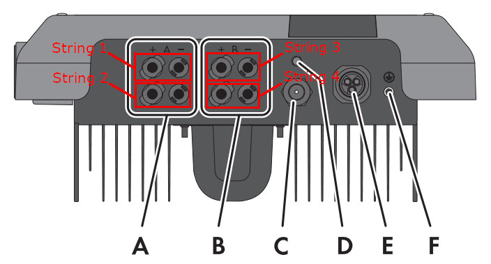
Table 1: Technical brochure for the SMA Sunny Boy inverter family
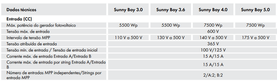
The inputs for strings 1 and 2 as well as 3 and 4 are internally connected to the inverter in parallel, each pair operating on one MPPT only. In a system with two strings, the installer must be careful to connect each string to an MPPT if parallel connection is not desired.
You must also pay attention to the current limit and voltage range per MPPT informed in the manual. For the Sunny Boy inverter shown, the current limit per MPPT is 15A and the operating voltage range is 175V to 500V. Respecting these limits will ensure the best efficiency and safety of equipment operation.
Become a Canal Solar partner. Contact us: [email protected]


6 Responses
I want to start in the photo voltaic business as an installer and then expand in the sector: selling, designing, etc.
The maximum input voltage of 600V, (using the same Sunny boy 5.0 inverter as an example) is this voltage per MPPT or the sum of the voltages of the 2MPPTs?
In each MPPT can I enter 600V?
Hello, Marcelo, how are you? will be the sum of the voltages
What would happen if the same string was connected to 2 inverters simultaneously?
Hello Vinicius, in this case it won't work
My interest is only in knowledge, I do not intend to enter this market. I am analyzing proposals for installation in my home and as knowledge takes up no space, there is nothing better than learning for a better evaluation.