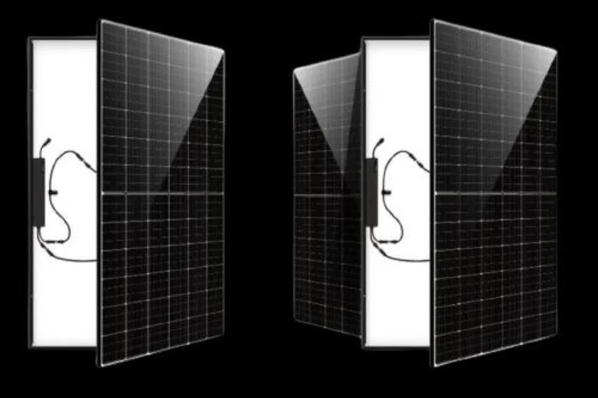
the term mismatch, translated as “incompatibility”, refers to the mismatch between the powers of the photovoltaic modules in an array or a string.
As no solar panel is the same, photovoltaic modules with the same nominal power may have different real powers. Lower power panels cause generation losses in the set.
When leaving the production line, the modules are classified according to their power, which is measured using a light flash test.
Solar panels are tested, one by one, in factories. In Brazil, to receive the INMETRO seal [1], a photovoltaic module can vary in its nominal power from -5% to +10%. For example: a 340 Wp module can actually have a power between 323 Wp and 374 Wp.
Although this difference between modules with the same nominal power can be up to 15% when leaving the factory, the level of mismatch may increase over time.
It is known that modules degrade year after year. This degradation does not occur uniformly and, therefore, each year the level of mismatch between modules in a string may increase [2].
O mismatch power of photovoltaic modules
The ideal situation would be to use modules with the same electrical characteristics in solar plants. In practice, it is known that there will always be a dispersion of the magnitudes of these characteristics due to natural variations in manufacturing processes, which causes the mismatch of power.
To illustrate, figure 1 shows the result of a study on an 815 kWp photovoltaic plant [3].
Half of the plant's modules were tested and their maximum power currents (Impp) were measured. These 2,100 modules come from 3 different batches and have the same nominal power. However, there is a natural dispersion due to manufacturing processes.

Connecting different modules to the same string makes generation always limited to the module with the lowest current (which is normally also the one with the lowest power).
It is interesting to note that even choosing modules from the same batch – for example, the red batch – there are mismatch current between the modules.
This shows that there is not only mismatch in peak power values, but also in other electrical parameters of the modules, such as maximum power current.
The modules, whether leaving the factory or during the certification process, are not classified according to their current – only the power is taken into account.
How optimizers work to mitigate losses due to mismatch
As previously mentioned, when working with photovoltaic modules connected in series, the operating current of the string will be limited by the module with the lowest current generation capacity.
In a traditional system, modules connected in series must operate with the same current. In a system with optimizers, the optimizers connected in series must also work with the same electrical current. Therefore, the same value of current passes through the output of all optimizers.
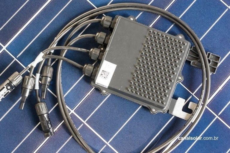
The optimizer, which is a DC-DC converter, relates the input voltage and current to the output voltage and current. If the output voltage is greater than the input, the output current must be less than the input.
Considering the lossless optimizer, the product between input current and voltage must be equal to the product between current and output voltage. That is, the input power is equal to the output power.
Figure 2 shows an example of a system with three optimizers in which the three modules do not present mismatch.
Each module works on its MPP (maximum power point or maximum power point) and each optimizer works with the same voltage and the same current. In practical systems there are typically around seven or more optimizers connected in series (and not just three, as illustrated below).
The input voltage value in inverters used with optimizers is defined according to the AC network to which the inverter is connected (two-phase, three-phase, 127V/220V/380V). The input voltage is generally above 350V.

If one of the modules presents mismatch of 5% in relation to the others and if its operating voltage is maintained, the current passing through the optimizers tends to decrease, making the other modules work outside their MPPs.
However, with the performance of the optimizers, the module with mismatch has its voltage modified, so that the optimizers' output current remains balanced. All optimizers work with the same current, but with different voltages – and all modules operate at their respective MPPs.

Even with the variation in the voltage of the optimizers, the voltage in the inverter remains the same, at 180 V in this example.
The optimizers with higher power modules have a higher voltage (61 V), while the optimizer with the lower power module has a lower voltage (58 V).
It is worth noting that the input of the optimizers (connected to the solar panels) work independently of the output (connected to the other optimizers and the inverter).
In practical terms, it is possible to understand that the optimizers' input is concerned with the MPPT and making the modules work at maximum power in any situation.
While the output of the optimizers is concerned with maintaining the voltage and current at the inverter's most efficient operating point.
The onboard control system ensures that the best generation conditions for each optimizer are automatically adjusted.
Thus, optimizers are able to detect any small variation in the modules and readjust themselves to ensure that each module works generating maximum power.
In the second case, each optimizer individually performs the MPPT (maximum power point monitoring or maximum power point tracking).
With this, it is possible for each module to work at its maximum power, regardless of the level of mismatch existing between the system modules.
It is important to remember that, due to this functionality, the system with optimizers can work with modules from different manufacturers or modules with different orientations and inclinations.
Case study: analysis of the effect of optimizers
A case study was carried out in the PVSyst software with the aim of analyzing the minimization that optimizers can perform on generation loss due to mismatch of photovoltaic modules.
PVSyst simulates the photovoltaic system with a value of mismatch preset of 1%. However, the user can modify this value to get an idea of the impact of the mismatch in the generation of electrical energy.
In the software the level of mismatch selected is applied both positively and negatively to the modules, randomly, making the statistical model the closest to what would occur in a real application.
The simulation of a system with 10 modules of 400 Wp (4.0 kWp) was carried out in PVSyst in a system with optimizers.
In the system, an optimizer was connected to each module, totaling 10 optimizers. These 10 optimizers were connected in series and connected to a 3.7 kW inverter.


The value of mismatch generally used in simulation is between 1% and 2% [5]. For this case study, a mismatch of 1.5% was used.
The chosen value is very typical for all photovoltaic installations, especially for the architecture adopted in this evaluation. In larger systems, with modules from different batches, this value may be higher.
The result was a generation of 5307 kWh/year or 530 kWh/year/module. In the report, where the software details the losses, the percentage of losses per mismatch: 0,00%.
Below is an excerpt from the report provided by PVSyst in this simulation, indicating that the loss due to mismatch of modules is null:
In contrast, a system of the same power based on strings conventional models, with the same number of modules, presents loss due to mismatch of 1.6%, as seen in the excerpt below from another report generated by PVSyst:
These simulations show the gain from avoiding the mismatch in the first year of installation. This gain grows annually, as the mismatch level also increases over time.
The system was simulated for the tenth and twenty-fifth years after installation, when the mismatch has already evolved year by year. A loss of 2.97% of energy was detected in year 10 and was 5.90% in year 25, both due to mismatch of the modules.
Mismatch loss of 2,97% calculated in the tenth year of operation (without optimizers):
Loss for mismatch of 5,90% calculated in the twenty-fifth year of operation (without optimizers):
Conclusion
O mismatch, or the incompatibility of photovoltaic modules is a loss mechanism present in photovoltaic systems.
This problem is not always considered when designing the photovoltaic project and is accentuated with the degradation of the modules over time.
Systems with optimizers mitigate this problem due to their ability to track maximum power at the module level.
In the case study presented, losses would be 2.97% in the tenth year of operation and 5.90% in the twenty-fifth, while the system based on optimizers presented a loss of mismatch null in the simulation performed.
References
- [1] INMETRO. Ordinance No. 004, of January 4, 2011, accessed on 06/25/2020.
- [2] P. Manganiello, M. Balato and M. Vitelli, “A Survey on Mismatching and Aging of PV Modules: The Closed Loop,” in IEEE Transactions on Industrial Electronics, vol. 62, no. 11, pp. 7276-7286, Nov. 2015.
- [3] P. Perotti, R. Fin, G. Grazia, “Monitoring and evaluation of economic impact in the reduction of mismatching in a PV plant located in Northern Italy”, 26th EUPVSEC, 5-9/9/11, Germany.
- [4] IV Curve Tracing vs. SolarEdge Real Time Monitoring. SolarEdge Technologies. Version 1.0. April, 2019.
- [5] D. Picault, B. Raison, S. Bacha, J. de la Casa, J. Aguilera, “Forecasting photovoltaic array power production subject to mismatch losses”, Solar Energy, Volume 84, Issue 7, pp.1301- 1309, 2010.


