
Most likely, the term oversizing or overloading is already present in your daily life if you work in the photovoltaic sector.
One of the main, if not the main question, that we, distributors, receive from our partners and customers when we present a photovoltaic inverter is: “How much oversizing can this equipment support? 20%? 30%? 50%? The answer is “it depends”.
It's not what he wanted to hear at first. But why is it not possible to present a DC overload value as absolute?
And, assuming this premise is true, even if the inverter supports 50%, 60%, is this always the best option? In fact, what does oversizing mean and how should it be analyzed?
We will demonstrate this throughout this article, presenting numbers and simulations in PVsyst to support our arguments and help the reader to optimize their photovoltaic system, choosing the best inverter option.
Defining oversizing and clipping
Oversizing, overloading, FDI (inverter sizing factor) or even overloading are some of the nomenclatures commonly used in everyday life in our sector. Simply put, oversizing means carrying out an installation with a photovoltaic module power (Wp) greater than the rated power of the inverter.
But what is the reason for doing this? Aren't we wasting energy? Below we will analyze the generation curves of a photovoltaic system comparing the two situations: with and without oversizing.
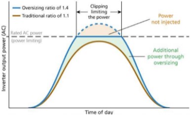
In the same figure we see the situation with oversizing (blue curve), when the peak power of the photovoltaic modules is higher than the input power of the inverter. It is observed that most of the time the oversizing system delivers more power compared to the first case.
This represents greater energy generation throughout the day, including mornings and late afternoons. But what happens during peak hours, when the power of the photovoltaic modules exceeds the power of the inverter? The inverter will not output more than its rated power.
Therefore, what happens is called clipping, when the inverter limits the output power of the photovoltaic modules so that the power delivered to the electrical grid is limited to the nominal value of the equipment, as also illustrated in Figure 1. But how is this done by the equipment? How does the inverter make this adjustment? We'll see next.
What happens when we oversize a photovoltaic system?
When the inverter reaches the limit point of its rated power and there is more power available in the modules (area in red in Figure 1), what happens? Is this excess value transformed and dissipated in the form of heat, heating the equipment? No, this does not happen, as many people think.
We know that the inverter is constantly analyzing the voltage and current parameters received from the modules, adjusting and seeking the maximum power point. In these cases, the inverter adjusts its DC voltage value so as not to exceed the maximum power of the equipment.
As we can see below, we have the IxV curves of the photovoltaic modules, where point A would be the inverter's optimal operating point, when it would deliver the maximum possible energy to the installation. On the other hand, point B represents a situation of limiting the power of photovoltaic modules, when the inverter adjusts the DC input voltage so as not to exceed the maximum permitted power.
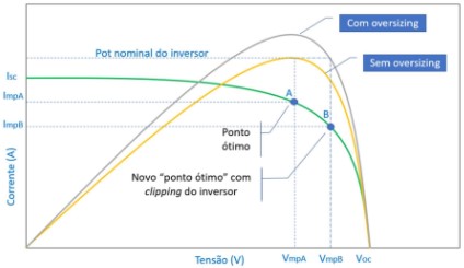
What the inverter does is increase the string voltage value from point A to point B, reducing the current injected by the modules, so that the instantaneous power in the gray curve (Figure 2 – with oversizing) is the nominal power value of the inverter. As a result, the equipment will continue to work within its limit values and no excess energy will be produced or dissipated in the form of heat or any other form that could harm the equipment.
But perhaps you are wondering: “Wouldn't it be more interesting to install a higher power inverter, so that at the moment with peak power available in the photovoltaic modules I could take advantage of all this energy generation potential? In other words, wouldn’t it be better to install a system with a 1:1 relationship between the power of the modules and the nominal power of the inverter?”
Why is oversizing photovoltaic modules a good option?
There are several factors that corroborate the use of oversizing modules in relation to the inverter in photovoltaic systems:
- STC Conditions: The power information contained in the photovoltaic modules' technical sheets is provided for parameterization purposes, so that we can compare different manufacturers under the same reference. But these values are reached very rarely during the year. Due to temperature losses and low irradiance, the power supplied by the modules most of the time is lower than its peak value in STC;
- Module degradation: As can be seen in the technical sheets, all modules have a degradation in their power over the years (somewhere around 2%-2.5% in the first year, and 0.4-0.5% in the remaining years, reaching the end 25 years of guaranteed performance with something around 80-85% of its nominal power stated in the technical data sheet. In other words, over the period of operation, this oversizing will be smaller and smaller;
- Maximizing energy production: In many cases, oversizing allows you to maximize the energy production of the photovoltaic system and reduce the LCOE (levelized cost of energy). Furthermore, in many cases there is a limitation on the capacity installed on site, or a desire not to exceed a certain demand value (75 kW in microgeneration or 5 MW in DG plants) for economic purposes. Therefore, oversizing becomes a valid option for this aspect as well.
Is it safe to oversize?
As long as the inverter limits stated in the technical sheet are respected, there is no risk in oversizing the inverter. In many cases, as we will see below, oversizing is even beneficial, if well designed. Furthermore, no inverter will lose its warranty due to correct oversizing.
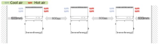
It must be considered, however, that in these cases the inverter will operate closer to its nominal power for most of the time, which requires even more attention to installation and operating conditions (suitable location, good ventilation, preventive maintenance, etc.) to great functioning.
Some case studies
After we understand the concepts of oversizing, let's analyze some application cases to understand why the question: “What oversizing does this inverter support?” There is no single, definitive answer for all cases. All of the following simulations were carried out using the PVSyst software together with the .OND and .PAN files provided by the manufacturers.
Furthermore, as the objective of the article is to present the differences with different loads, losses due to shading were not considered in these simulations. The location chosen for the simulation was Salvador/BA. The results could be different in other locations.


The first analysis we will do will be using the Sungrow SG8K3-D inverter, with a nominal power of 8.3 kW, with 2 MPPT's (up to 3 strings in total), together with Canadian Solar CS3U-360P modules. This inverter has three individual inputs, with a DC voltage limit of 600 V. Below is some information from the technical sheet of this equipment, which we must consider when sizing the strings of photovoltaic modules:
Table 1 – Sungrow SG8K3-D inverter DC input data. Source: Sungrow
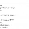
Points to consider
- Maximum input voltage:600V – Value that should not be exceeded at any time during inverter operation. The module's open circuit voltage (Voc) corrected for the lowest local temperature must be considered;
- MPP voltage range for rated power and rated input voltage:voltage values at which the inverter will work at its optimum operating point. We carry out the following dimensions:
Table 2 – Dimensioning data carried out
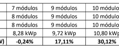
First, we simulated with a power very close to the equipment's nominal power (23 modules = 8.28 kWp). Cases were also simulated for 27 modules (117.11%), 30 modules (130.12%) and finally 33 modules (143.13%), the limit that is possible with these modules without exceeding 600 V maximum voltage, corrected to 0 ° C minimum temperature.
A simple change of region could be enough to impact this maximum limit, which proves to us that there is a fixed result. Below we have some generation and efficiency parameters provided by PVSyst: energy (kWh) generated during the first year of system operation:
- kWh/kWp/yr: Amount of energy generated in the year in relation to the installed peak power. Parameter used to compare systems with different powers;
- PR (performance ratio): Parameter that indicates the efficiency of a system. The closer to 1, the more efficient the system will be.
In summary, we present the simulations obtained in this case in the following table:
Table 3 – Results obtained from the simulations
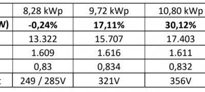
The first point we want to draw attention to with this simulation concerns the kWh/kWp/yr index. As we can see, the more modules inserted, the greater the generation (kWh), but after a certain point, the system will produce less energy per additional kWp and with a lower PR.
Furthermore, we can see that the closer we get to the optimal voltage value (360 V in this case), the more efficient the system will be. “So does that mean there is no reason for me to oversize this inverter by 43.13%, given that with 30.12% it is more efficient?” Not necessarily.
An individual economic analysis of each case is essential, as the energy gain may offset the higher cost, even with a slightly lower yield, due to limitations in the input standard, for example. “So I can consider that the SG8K3-D inverter supports a maximum of 43% oversizing.” No, it is not possible to say that.
Let's do the same analysis, with the same equipment, but with 440W JA Solar modules.
Table 4 – Simulation configurations with JA Solar modules

In this case, we can see that due to the maximum voltage limitation, we were able to place only 30 modules of this model. And even so, we reached a peak power of 13.2kWp, with almost 60% of oversizing:
Table 5 – Results obtained in simulations with JA Solar modules
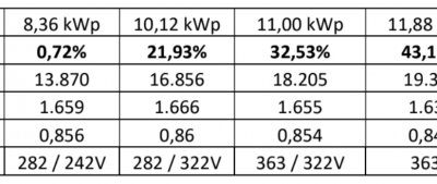
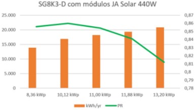
But as we can see from the PR index (green curve in Figure 4), it drops considerably in this case, even with greater energy generation (orange bars). The kWh/kWp ratio decreased significantly, due to the fact that the inverter operates outside its optimal range.
Once again, it is important to emphasize that a financial analysis is necessary to determine the best option for a photovoltaic system, and that it is analyzed on an individual case by case basis. There is no absolute truth in the simulations above that suit all installations. Various design parameters such as module model, inverter model, installation location, etc. must be carefully analyzed.
To further emphasize the particularity of each case, we will analyze the same inverter working practically at its nominal power, with 100 405 W Trina Solar modules. The simple different configuration of the module arrangements impacts almost 1,300 kWh more generated in the first year.
There is 2% more energy just because the system works closer to its optimal operating voltage, with a better distributed arrangement.
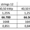
Table 6 – Simulation configurations with Trina Solar modules
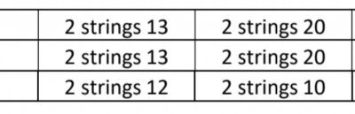
Table 7 – Results obtained in simulations with Trina Solar modules
Conclusion
As you can see, well-performed oversizing is essential for better performance of the photovoltaic inverter, an important topic covered in solar energy courses.
There are several factors related to the construction of modules and inverters that justify this. And the idea of the article is precisely to bring this topic up for debate, so that a careful analysis can be carried out on a case-by-case basis, instead of simply assuming that a certain percentage of oversizing is ideal for any inverter, anywhere.
And also show that, sometimes, it may be interesting to oversize the equipment beyond its optimum point, as it will be financially rewarding. Imagine a case in which the load installed in the consumer unit is 75 kVA or 112.5 kVA (very common values), and a change in this would imply costs for network reinforcement works and also change the customer's tariff group, with the need for pay the contracted demand.
It may be more financially interesting to install oversizing 40%, 50% or 60% on photovoltaic modules, achieving greater energy generation without having to make adjustments to the utility network, even if the inverter operates with an efficiency slightly lower than its maximum efficiency.
Let's analyze the graph below, obtained with a Sungrow SG40CX inverter and 440 W JA Solar modules.
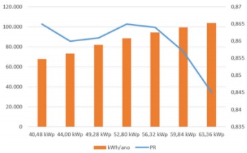
According to the voltage and current limits of the equipment provided in its technical sheet, it would be possible to install up to 63.36 kWp of modules (8 strings of 18 modules) within the limits of the equipment.
As you can see in the orange bars, we would be continually generating more energy, but at what price? The system performance after a certain point decreases with the increase in installed power. Is it possible to install? Yes it is. Is it financially viable? This answer needs to be sought for each case.
After regulatory changes by ANEEL (National Electric Energy Agency), this analysis will become essential, as a system that is not optimally sized may not be economically viable. O concept of LCOE (Levelized Cost of Energy) becomes very important in this analysis, to help define the correct oversizing. As we know, photovoltaic systems are primarily investments with expected economic returns.
References
- [1] R. Mounetou, IB Alcantara, A. Incalza, J. Justiniano, P. Loiseau, G. Piguet, et al., “Oversizing array-to-inverter (dc-ac) ratio: What are the criteria and how to define the optimum?”, Proc. Eur. Photovolt. Sol. Energy Conf. Exhibition, pp. 2813-2821, Sep. 2014
- [2] SOUZA, JP Oversizing and clipping in photovoltaic systems
- [3] J. Good and J.X. Johnson, “Impact of inverter loading ratio on solar photovoltaic system performance,” Appl. Energy, vol. 177, pp. 475-486, Sep. 2016
- [4] M. Hussin, A. Omar, S. Shaari and NM Sin, “Review of state-of-the-art: Inverter-to array power ratio for thin-film sizing technique”, Renewable Sustain. Energy Rev., vol. 74, pp. 265-277, 2017
- [5] Sungrow inverters user manuals and data sheets. Available in https://sungrowpower.com/pt-br Accessed in July 2020


One Response
Here in my system there was an oversize of 33%, 8 335w boards in a 2000w inverter resulting in it overheating. I removed a board and it resulted in the same generation and less heating of the Inverter, so I think that oversize is suitable to correct some obstacles such as the position of the panels, regions with a lot of cloudiness, etc.