
The objective of this article is to demystify and explain the objective and potential of oversizing. Oversizing is the term we use to designate the situation in which the solar modules are oversized in relation to the inverter power.
In other words, there are many more modules in the photovoltaic system than the inverter would be capable of receiving according to its rated power.
A consequence of oversizing and the clipping, which is the clipping or clipping of the inverter power curve, as we will see below. We will now discuss the advantages, disadvantages and limitations of the oversizing.
Instead of empirically establishing an additional module power over the nominal inverter power, we will see why it is necessary to evaluate the best relationship between module power and inverter power.
Seeking to optimize projects, the ratio between nominal peak power (in STC – standard test conditions) of the photovoltaic modules and the input power of the inverter. Increasing this ratio is equivalent to reducing the FDI (inverter sizing factor), defined as:
FDI = Inverter input power / Peak power of photovoltaic modules
In other words, the higher the power of the photovoltaic modules in relation to the power of the inverter, the lower the FDI. Normally in photovoltaic projects the FDI is less than 1, indicating that the inverter power is generally lower than the power of the photovoltaic modules. This is natural, since the nominal peak power of the STC modules (1000 W/m2 and 25 ºC cell temperature) is rarely reached.
In some cases, however, an even lower FDI is sought, with a greater increase in module power over the inverter power. This can increase the technical-economic relationship, allowing the levelized cost of energy to increase (LCOE – levelized cost of energy) and the internal rate of return (IRR), which are economic indicators widely used in the evaluation of photovoltaic systems and plants. [1]
One of the main difficulties for photovoltaic system designers is finding the ideal FDI, or the ideal relationship between module power and inverter power, considering all the technical and economic parameters of a photovoltaic project, as well as the technical characteristics or restrictions of the inverters. In fact, for each location, due to the specifics of the site, the ideal settings are different [1].
What is it oversizing?
The word oversizing literally means oversizing. It is also possible to find other terms in the literature to designate the oversizing as: overpaneling, overloading or overbuilding. In the context of inverters for photovoltaic systems, this involves oversizing the peak power of the photovoltaic array (set of system modules) over the rated power of the inverter.
While most inverters can handle the oversizing, in some cases there are important limits for this to be done. For example, the output voltage of the photovoltaic array strings must not exceed the maximum allowable voltage at the inverter input. Furthermore, the maximum short-circuit current of the PV array should not exceed, in principle, the maximum input current of the inverter.
The correct definition of FDI (or the amount of oversizing) is one of the most important aspects to be defined at the initial stage of the project, considering all site parameters and respecting all technical limitations of electrical components to optimize the balance between costs and revenues [1].
What is it clipping?
The increase in the ratio between module power and inverter power (or the consequent reduction in FDI) exposes solar inverters to a set of photovoltaic modules whose power and short-circuit current are greater than those that the inverter would theoretically withstand. . Depending on the intensity of the oversizing will occur clipping, which is nothing more than the power limitation imposed by the inverter on the photovoltaic modules.
The generation power is limited to the maximum power of the inverter and the power x time curve (at the inverter output) is clamped or flat. This power limiting effect (clipping) in inverters occurs with greater probability and for longer periods the greater the oversizing, as shown in Figure 1 [1].
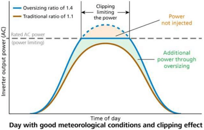
Since the additional energy obtained through the oversizing (area of the blue graph with the solid line) is greater than the energy lost as a result of the clipping (area of the graph under the dashed blue line), we will have a relationship of oversizing (or a favorable FDI).
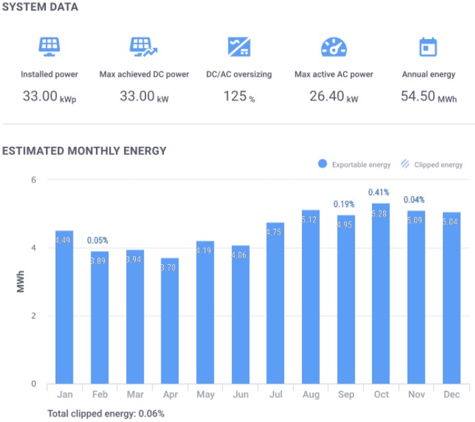
Furthermore, it is important to note that the clipping it can only occur on some days of the month and some months of the year. For example, there may be clipping on some summer days. This can be verified through simulations, such as the one in Figure 2 below.
The inverter has to dissipate energy and will heat up when the clipping?
In response to this condition of clipping, an inverter simply adjusts the operating point of the photovoltaic modules in order to limit the power generated. In other words, the inverter does not let the modules produce more power than the inverter can handle.
Therefore, when the clipping There is no excess energy dissipation in the inverter, as some people might think. This occurs because during generation limitation, the inverter limits the input current from the PV array, moving the array's operating point to an operating point of higher voltage and lower current along the IV curve of the array, moving away from the maximum power point of the arrangement [2], as shown in Figure 3.
Overheating of the inverter (under normal conditions) may occur during operation. clipping only due to the fact that the inverter works longer at its maximum power, but not due to excessive energy processing.
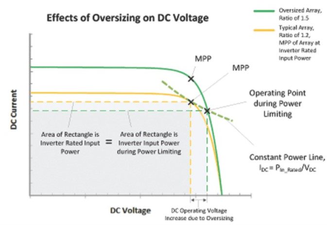
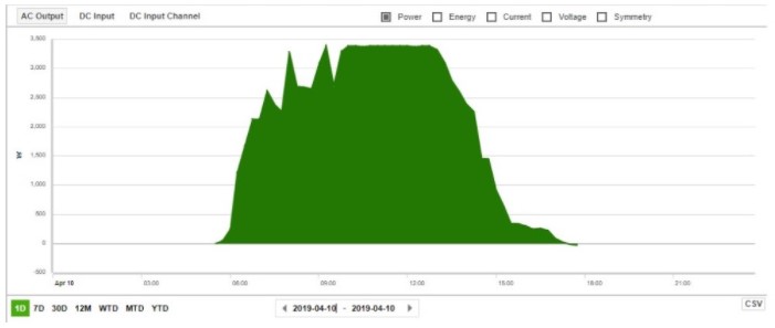
Figure 4 below presents a practical example of a photovoltaic system in which the power curve was limited to a power of approximately 3.4 kW. This cut is an indication that the clipping.
Like the Do inverters work with oversizing?
O oversizing occurs, as we have previously discussed, when the peak power in STC of the set of photovoltaic modules (PFV,STC) is higher than the maximum power of the inverter (PINV,CA). The inverter power considered can be output (AC) or input (DC), depending on the desired definition or according to the literature consulted. The maximum output power of the inverter corresponds to its nominal power specified in the catalog or in its datasheet.
Therefore, for an inverter with maximum AC output power PINV,CA connected to a photovoltaic array with PFV,STC power, this inverter is oversized if:
PFV,STC > PINV,CA
The factor of oversizing (Foversizing), which is the inverse of FDI, can be defined according to the following expression, where PFV,STC is the peak power of the photovoltaic array in STC and PINV,CA is the maximum AC output power of the inverter:
Foversizing = PFV,STC / PINV,CA
Photovoltaic inverters are designed so that the output power does not exceed the maximum AC power values (PINV,AC). In many cases the oversizing of photovoltaic modules (or undersizing the inverter) can increase power generation in low-light locations, where the real power of the photovoltaic modules will always be below the peak power in STC.
Installing a smaller inverter for a given array or, equally, installing more power modules for a given inverter, can have benefits and is perfectly acceptable. However, excessive oversizing of the inverter, outside the technical requirements established by the manufacturer, can have a negative impact on the total energy produced and the useful life of the equipment.
The cooling system of a PV inverter must be correctly designed, allowing it to operate for a long time at its maximum rated power. In low quality equipment, photovoltaic systems with oversizing may cause the inverter to shut down if critical temperatures are reached.

This behavior, provided by a safety system, protects the inverter's internal components against melting due to excessive heat dissipation. High temperatures in inverters can arise when forced ventilation fails or is insufficient, due to fan malfunction, obstruction of ventilation areas or as a result of high ambient temperatures.
O oversizing and photovoltaic modules
Photovoltaic modules do not constantly work at their rated peak output power. The power output of the modules is affected by the weather, the position of the Sun during the day, the conditions of the installation site and the orientation and inclination angles, among other things. Furthermore, the module's output power will decrease due to dirt and shading.
In places with high presence and dust (mining plants, quarries, etc.) with average annual losses greater than 4% to 6%, it is also recommended to be careful with the oversizing. The risk is to get a oversizing It is clipping in the inverter greater than expected, especially after cleaning the photovoltaic modules or after heavy rain.
Additionally, the output power of photovoltaic modules decreases over time due to their natural degradation, while the power rating of the inverter will remain constant. This will progressively reduce the DC/AC ratio. As a result, the average losses per clipping over the 25 years of module warranty will be less than the losses in the first year. Remembering that normally the energy production guarantee of PV modules covers a production loss of up to 20% of the nominal value of the module over 25 years.
Why oversize?
The main reason for overloading an inverter (or oversizing the PV modules for a given inverter) is to bring it to full capacity more frequently. This will maximize power output in low light conditions, allowing for the installation of a smaller inverter for a given PV array.
O oversizing of the photovoltaic array is not a requirement, but an experienced designer of photovoltaic systems may choose to use an inverter with a power lower than that of the solar panels to employ a lower power inverter (reducing the cost of the system) or, in the extreme case of one oversizing It is very important to provide a photovoltaic system that operates at the power limit most of the time, producing more energy throughout the day.
Carry out the oversizing of photovoltaic modules makes economic sense in terms of balancing system component savings. Using module power greater than inverter power helps improve costs per kWh generated associated with inverters, cabinets, internal infrastructure and specialized equipment. This allows you to design an optimized plant in order to achieve the best IRR and the best LCOE, maximizing the project's financial results.
Oversizing of some inverters
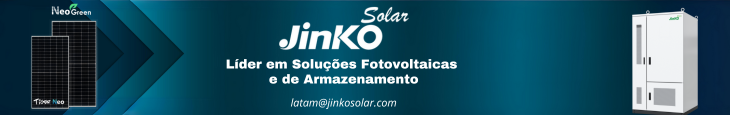
Inverter manufacturers, in their specifications, allow a oversizing quite high, sometimes up to 175%. SolarEdge, for example, allows a oversizing up to 135% (Figure 5). For your single-phase inverters from the HD-Wave line, the oversizing up to 155%. O oversizing on SolarEdge inverters will not harm the inverters. Maintaining this limit will guarantee the useful life of the inverter and is necessary to keep the inverter covered by its warranty [3].
However, this does not mean that using these percentages of oversizing are a recommendation for oversizing excellent. In many cases, you can design the system with a oversizing smaller to ensure that the inverter does not present clipping, or you can limit the clipping to an optimal value, considering module degradation and other factors.
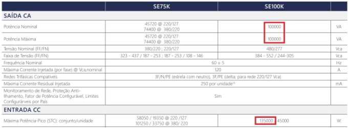
O oversizing maximum allowed is a parameter that varies from inverter to inverter. Therefore, before installing a solar panel power greater than the inverter power it is necessary to consult the datasheet of the equipment. For example, Figure 6 below presents an excerpt from a data sheet for a photovoltaic inverter whose nominal output power is 28.6 kW.
This inverter has two MPPTs, that is, two inputs with individual maximum power tracking. Each input supports a maximum power of 16 kW, so it is possible to install a maximum of 32 kW of nominal module power, respecting the nominal limit of the inverter (without oversizing).
According to Figure 6, the percentage of oversizing Maximum allowed is 111.88%. If a photovoltaic array with oversizing of 120%, this condition may be harmful to the inverter. Consequently, the useful life of the inverter would be reduced or the inverter would suffer some damage and it would not be covered by your warranty.
Putting concepts into practice
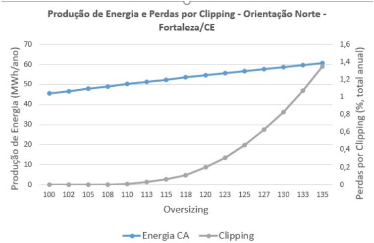
In the example in Figure 7 we have the result of a simulation for a system oriented to the North, with an inclination of 15 degrees and with meteorological data from Fortaleza/CE. We can see that by increasing the size of the PV array from 26.4 kWp to 35.64 kWp (with an inverter capacity of 26.4 kWp), the energy production grows from 45.62 MWh/year to 60.69 MWh/year (33.03%). In the same range, losses due to clipping increase from 0% to 1,35%. In this case we observe that, despite there being a loss due to clipping of 1.35%, it is possible to estimate a production gain of 33.03%.
In the example in Figure 8, we have the result of a simulation for the same system, now installed on a gable roof, with half of the modules installed on each roof — that is, with an east-west orientation. The slope of each water remains at 15 degrees and we continue with meteorological data from Fortaleza/CE.
We can see that by increasing the size of the PV array from 26.4 kWp to 35.64 kWp (with an inverter capacity of 26.4 kWp), the energy production grows from 43.36 MWh/year to 58.68 MWh/year (35.33%). In the same range, clipping losses increase from 0% to 0.34%.
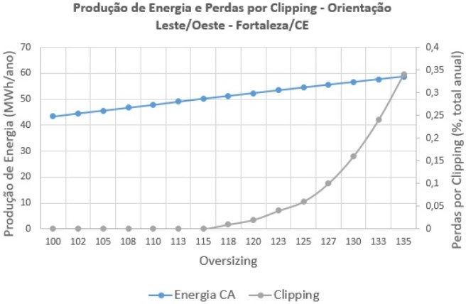
In this case we observed that, for the same system now installed with east-west orientation, the percentage of energy gain is greater than in the previous case. With the addition that the loss of energy due to clipping now it is only 0.34%.
Even so, we must take into account that if it is possible to choose the installation orientation, even with greater losses due to clipping, the greatest generation potential is in the case of Figure 6 (roof facing North).
However, if it is not possible to choose the orientation and we fall into the case of Figure 7 (east-west roof), we can observe that there is the possibility of using a oversizing even higher, if the inverter allows it. This would lead us to increase the generation potential of the photovoltaic system without additional costs for inverters and inputs, among others.
Conclusions
The two simulations presented show that the oversizing It is a powerful design tool, as long as it is used in accordance with the technical requirements of the project. In case of a module power greater than the inverter power (or an FDI less than 1), even if greater losses due to the clipping of energy have to be accepted, especially during the first years of operation of the PV system, they are largely compensated for throughout its useful life.
In fact, a high oversizing allows maintaining higher energy production throughout the useful life of the system, while the power of the photovoltaic modules degrades over time. Furthermore, the system produces more energy in the early morning, late afternoon and during other periods of low or medium levels of solar irradiation (see Figure 1).
On the other hand, excessive oversizing can negatively affect the inverter's energy production. One clipping excessive results in loss of energy generation (little use of the generation potential of the photovoltaic array). Excessively overloading the inverter also causes the inverter to operate at high power for longer periods, affecting its lifespan.
Operating at high power also increases inverter heating and can heat up the room. Inverters will reduce their maximum power generation in case of overheating. This generation reduction has a specific term, called “power de-rating”, which will be covered in future articles.
The good news is that inverters have thermal management architectures to control internal temperatures and protect equipment during extended periods of full load operation.
These measures also work to help preserve the life of temperature-sensitive components. Inverters sense temperatures of critical components and have programmed setpoints that control fan speed and power limiting as a means of regulating the internal temperature of the equipment [2].
This article is far from exhaustive on the subject. There is still a lot to be discussed in detail and in greater depth, especially considering the financial aspects and technical restrictions. However, we hope that this text will be a source of reference to demystify some concepts about oversizing It is clipping in photovoltaic systems.
References
- [1] R. Mounetou, I. Bejar Alcantara, A. Incalza, JP Justiniano, P. Loiseau, G. Piguet, A. Sabene, “Oversizing Array-To-Inverter (DC-AC) Ratio: What Are the Criteria and How to Define the Optimum?”, 29th EU PVSEC 2014, 22 – 26 September 2014, Amsterdam.
- [2] J. Fiorelli, M. Zuercher-Martinson, “Supersize It – How oversizing your array-to-inverter ratio can improve solar-power system performance”, Solar Power World, pp. 42-46, 2013. [3] SolarEdge, “Technical Note – Oversizing of SolarEdge Inverters”, July, 2016.


7 Responses
Congratulations on your article.
I have a 50 KW three-phase Sofar inverter on the coast of Bahia.
On certain days of the year it generates up to 50kW. I only observed this a few months ago and from July to November he was clipping at 40kw. Now in December it is clipping at 35.1Kw. What would be the most accurate explanation? The temperature?
thanks in advance
Hugo
Good afternoon, Hugo, how are you? Clipping can be caused by several factors, one of them is temperature, to have a more accurate diagnosis, the ideal is to carry out tests to check the reason for the inverter overload.
When the text says that “” there are important limits for this to be done. For example, the output voltage of the photovoltaic array strings must not exceed the maximum allowable voltage at the inverter input. “” if this premise is true, where are you going to do this oversizing??? if I cannot exceed the voltage and current limits of the inverter…. it wasn't clear. can or can not ??
It's Solaredge Designer.
Good evening João Paulo!
I still really cannot understand the reasons for seeking to undersize the nominal power of the inverters in relation to the generation of photovoltaic modules.
Even though it seems like the same thing, I understand that we should size the generation of photovoltaic modules according to what was raised, and add something like 20% in this generation to compensate for the losses in the panels' performance throughout their useful life (25/30 years). Based on this power, we should choose an inverter with the closest possible power to this number, ensuring that in any lighting conditions, all the energy generated by the modules can be converted, without any loss, whether due to low light or clipping.
Therefore, I do not understand the premise stated in the text that “we would gain energy production by overloading an undersized inverter, as we would be taking it to its full capacity more frequently, maximizing its energy output in low light conditions”.
If you could clarify me, even if privately, I would appreciate it, as I would not like to make mistakes in the dimensions or specify inverters that are more expensive than necessary.
Thanks!
Hello good afternoon. Fantastic article. But I have a question: What software did you use to simulate figure 02?
Congratulations, João Paulo, for sharing your knowledge in a succinct and objective way. It partially clarified my doubts.
I'm not an expert in the area, but I'm analyzing a system that has 100 kWp PV installed and 5 hybrid inverters of 15 kW each.
The curve becomes “clipped” when generation reaches 60 kWh. I don't know what the reason was. Would it be a restriction imposed by the Concessionaire regarding production (micro, mini, etc.)? I think it's a waste that you have an installed capacity of 100 kwp and limit it to 60!
thanks.