With the continuous increase in the operating current of photovoltaic modules, reliable junction boxes are essential to ensure a service life of 20 to 30 years.
This article will look at what factors need to be considered when selecting a junction box for large format modules with different operating currents.
Junction box rated current
According to the bypass diode test specifications of IEC 61215, the nominal current of a junction box must be greater than 1.25 × Isc for a single-face module.
For a bifacial module, the bifacial gain must also be considered according to the following equation (IEC61215 \ IEC61730:2021):
Ijbox = Isc x (1 + 30% * f) x1.25
Where 'Isc' is the short-circuit current of the module and f is its bifaciality factor. The bifaciality is normally around 70% ± 5%, and to allow a reasonable safety margin for the junction box, the current adopted for different modules is shown in the following table:
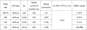
It can be seen that for modules based on 156.75mm, 166mm and 182mm wafers, there is a sufficient safety margin for the junction box. However, for a bifacial module based on a 210 mm wafer, there is no safety margin remaining, which indicates that in some cases, the module operating current will be greater than the rated current, resulting in possible failure of the module box. junction.
Diode design analysis of a junction box
In the case of 182 mm based modules, a 25 A junction box with a bypass diode for a given group of cells is reliable, with a sufficient safety margin (17.5%), as indicated above.


However, if a module's operating current increases to 18.4 A, the safety margin for the 25 A junction box becomes insufficient, requiring a significant increase in diode size.
Therefore, for an 18.4 A module, a parallel association of diodes is generally adopted, which has the disadvantage of the risk of uneven distribution of current between the diodes and their possible failure.
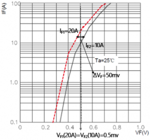
The following figure is a typical forward bias voltage curve of a 150 thousandths of an inch Schottky diode, model PANJIT 30SQ045. If the direct voltage drop is VF = 50 mv, the difference in the current passing through the two diodes will be 10 A, which could cause them to fail.
Junction box reliability analysis
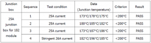
As the junction temperature is critical to the reliability of the junction box, several junction temperature tests were performed according to the following table for LONGi's Hi-MO 5 bifacial module, based on a 182 mm wafer. It can be seen that the 25 A junction box for the 182 mm module passed all tests even when the test current was increased to 26 A.
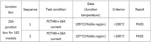
Furthermore, in order to simulate a complete set and outdoor aging factors (high temperature and humidity), a junction temperature test under PCT 48h (high pressure aging test) and current 26 A was carried out as established in table below. It can be seen that a 25 A junction box for a module size of 182 mm can be considered safe in outdoor conditions.
In summary, in selecting a reliable junction box for a large current module, safety margin, diode choice, and performance under adverse conditions are factors that need to be considered.
LONGi adopted the 25 A junction box for its Hi-MO 5 module after thorough analysis and testing, making the product compatible with a long life expectancy, reduced LCOE (levelized cost of energy) and high performance.