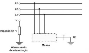
Grounding is a controversial subject, less because of its complexity and more because it is related to several aspects of an electrical installation. Also in photovoltaic arrays, grounding plays an important role in the safety and performance of these systems. There are three possible grounding schemes for a low voltage installation 1, 2, whether direct or alternating current, known as TN (TNC, TNS and TNC-S), TT or IT (Figure 1). Taking advantage of the characteristics of each system, comparing their advantages and disadvantages, values the designer, increasing the safety and efficiency of the installation.
The symbols used in the classification of grounding schemes are as follows:
- The first letter indicates the situation of the power supply in relation to the earth: T means a directly earthed point; I means isolation of all live parts from earth or grounding of a point through impedance;
- The second letter indicates the situation of the masses of the electrical installation in relation to the earth: T means directly earthed masses, regardless of the eventual earthing of a power supply point; N means masses connected to the grounded supply point (in alternating current, the grounded point is normally the neutral point);
- Furthermore, other (possible) letters inform the arrangement of the neutral conductor and the protective conductor: S means neutral and protective functions provided by separate conductors; C means neutral and protective functions combined in a single conductor (PEN conductor).
Among the three available schemes, the IT scheme is the least widespread, its use being closely associated with specific hospital environments, where it exists in the form of the famous medical IT, although its use is indicated in all installations where the continuity of power supply electricity, be a priority. In an IT scheme, all live parts are isolated from the ground or a power point is grounded through an impedance. Still in this scheme, the installation masses are grounded, in the following possibilities:
- Grounds grounded on the same grounding electrode as the supply, if it exists;
- Grounds grounded in their own grounding electrode(s), when there is no supply grounding electrode, or, because the grounding electrode of the masses is independent of the power supply grounding electrode.
For the safety of the installation, a protection device must automatically disconnect the power supply to the circuit or equipment it protects whenever a fault (between live part and earth, or between live part and protective conductor) in the circuit or equipment gives rise to a contact voltage higher than the relevant value of the UL limit contact voltage. This point is fundamental for understanding the IT scheme, because in this scheme it is desired not to automatically disconnect the supply when the first fault occurs, as long as the limit contact voltage remains at pre-established values. As in an IT installation the current from a single fault to earth, or to earth, has low intensity, it is not imperative to automatically disconnect the supply when the specific safety conditions established in ABNT NBR 5410:2004/2008 are met. In this case, it must also be ensured that dangerous contact voltages do not appear in the event of a second fault involving another live conductor. Therefore, when opting for the IT scheme so that the power supply is not disconnected in the event of a first fault, it is essential that it is located and eliminated as quickly as possible. So that automatic sectioning in the event of a first earth or ground fault is not mandatory, the value of the resistance of the earthing electrode of the masses (in ohms), multiplied by the value of the fault current intensity (amperes, A), resulting from a first direct fault between a phase conductor (in the case of AC) and ground, must be lower than the limit contact voltage at the point of occurrence of the fault:
RA. Id ≤ UL
Where:
- RA = Resistance of the grounding electrode;
- Id = Fault current intensity;
- UL = Contact voltage value at the fault point.
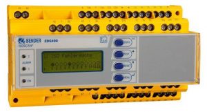
For faster identification and location of the fault, a supervisory isolation device (DSI) or supervisory fault location systems (Figure 2) must be provided for guidance by those responsible for the installation. This device must trigger an audible or visual signal, which must last as long as the fault persists. If there are both audible and visual signals, it is accepted that the audible signal can be cancelled, but not the visual signal, which must last until the fault is eliminated.
In the case of a second fault, the rules defined by ABNT NBR 5410:2004/2008 for TN or TT schemes must be followed, depending on how the masses are grounded. Despite all the technical issues, one should not lose sight of the fact that the objective of the IT scheme is to limit fault currents, making it possible to prevent automatic disconnection of the supply due to the first fault4. In other words, the continuity of the electricity supply is the great advantage when opting for this scheme, and extra security measures must therefore be adopted, which would not be necessary in TN schemes, since in this case there would be automatic disconnection of the supply already on the first fault. IT represents a choice for fewer interruptions in exchange for greater installation complexity, while maintaining the same security levels. To avoid the occurrence of a second fault, which is unacceptable, it is necessary that the first one be immediately identified, located and eliminated. As many accidents occur due to the difficulty in interrupting fault currents in direct current circuits, reducing their occurrence can be something operationally and economically interesting, which must be evaluated by the designer, as long as he does not carry the prejudice that the IT scheme It is a system exclusively used in hospital environments. Finally, the various functions of a grounding system must be evaluated within the limits of each standard. For example, the use of the IT scheme does not influence the efficiency of lightning protection (PDA)5 (Figure 3), whether in relation to lightning protection systems (SPDA) or in relation to surge protection measures ( MPS), whose grounding and equipotentialization characteristics must adapt to the characteristics of the IT scheme, something very simple to do.
References
- ABNT NBR 5410:2004 Corrected Version:2008, Low voltage electrical installations
- ABNT NBR 16690:2019. Electrical installations of photovoltaic arrays – Project requirements Requirements for an IT grounding scheme
- HACKL, Dieter. Operating photovoltaic installations safely and efficiently. https://www.bender.de/fileadmin/content/BenderGroup/Documents/Article/en/Beitrag_PHOTOVOLTAIK_engl_8str.pdf
- ABNT NBR 5419:2015. Protection against Atmospheric Discharges
new RDStationForms('interesse-em-cursos-articles-do-canal-solar-2a68fc32cce5530fe808', 'UA-145443047-1').createForm();