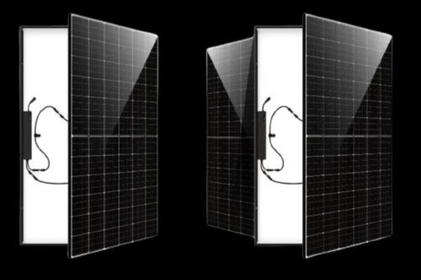
The insulation voltage standards of photovoltaic cables, modules and connections have evolved over time. The first commercially applied photovoltaic systems had an insulation voltage of 600 V as a standard, which later changed to 1000 V and, more recently, to 1500 V. The evolution of allowable voltages in photovoltaic systems was accompanied by an increase in the maximum voltages typically supported by inverters. Therefore, the designer has more and more options to work with strings from 1000 V to 1500 V. In general, when we increase the working voltage of the strings, the issue that deserves more attention is ensuring the insulation level of the components (cables , modules, switches and fuses, for example). When we increase the current, as a rule, we need to increase the section of the conductors and adapt them to the operating temperatures. So, if we imagine a set of modules to be arranged in series and parallel, when we choose to work with higher voltages (longer strings and fewer strings in parallel), we tend to work with smaller section cables and fewer fuses, circuit breakers and buses, a since we have fewer strings in parallel. To illustrate the advantage of working with 1500 V maximum voltage strings instead of 1000 V, we will compare the sizing of a photovoltaic system with two different inverter models. Let's take as a basis for this example the 125K-HV-5G (1000 V) and 125K-EHV-5G (1500 V) inverters, both produced by SolisSolis and with the same nominal power, but with different maximum voltages. It is important to note that this comparison is not made in terms of energy produced, since the selected inverters have different numbers of MPPT inputs, which may produce different results depending on the application. This will be a comparison of cabling complexity and cost. To make the comparison between 1000 V and 1500 V topologies less dependent on the specific inverter model in the example, let's imagine that it is necessary to parallelize all the strings in a string-box and leave with a pair of DC cables for the inverter. To compose this system we will use 400 Wp modules from Risen, according to the data below:
We will compose a 150 kWp system, leaving the 125 kW inverters slightly overloaded. To reach 150 kW of DC power we will need 375 400 W modules. We will start by determining the maximum number of modules in series, considering a minimum ambient temperature in the mornings of 10ºC. To do this, we will need to calculate the corrected Voc for this temperature:
Voc Variation = (Ambient Temp. – STC Temp.) x Voc Variation Coefficient
Variation = (10-25) x -0.29 = + 4.35%
Voc corrected by temperature = Voc_STC x (1+ 4.35%) = 50.7 V
The maximum number of modules in series for the 1000 V inverter will then be:
1000 / 50.7 = 19 units (rounding down)
And for the 1500 V inverter:
1500 V / 50.7 = 29 units (rounding down)
To arrive at the number of parallel strings required, we can divide the total number of modules by the number of modules per string for each of the situations: For the 1000 V system:
375 / 19 = 20 strings in parallel (rounding up)
For 1500V system:
375 / 29 = 13 strings in parallel (rounding up)
As all strings are parallel, it is mandatory to use fuses in at least one of the conductors. The 1000V system will then need 20 fuses, while the 1500V system will only need 13 fuses. This allows the choice of string-boxes that are physically smaller and have a lower cost per unit.
Let's imagine that there is an average distance of 10 m between the modules and the string-box. Therefore, the 1000 V system would need 200 m of positive conductor and another 200 m of negative conductor to connect the strings to the string-box. In the 1500 V system, we only need 130 m for the positive and 130 m for the negative. Using the conductor sizing criteria of the NBR 16690 and NBR 16612 standards, we also noticed another important difference between the systems: the conductor for the 1000 V system needs to be 95 mm² and the conductor for the 1500 V system can be 50 mm². Depending on the distance from the string-box to the inverter, the cost difference can be considerable. You can read more about cable sizing in the article Sizing of cables and protections in photovoltaic systems. Below is Table C.3 of the NBR 16612 standard:

Based on regulatory guidelines and project characteristics, we have the following results:
In this example, we compare 1000 V and 1500 V systems for a power of 150 kWp (and 125 kW inverter). If we considered a larger scale plant (like 6.5 MWp, for example), we would have much more significant differences: 303 fuses and 6000 m of cable less for the 1500 V solution compared to the 1000 V solution. ease of installation, design and handling of fewer cables on site.
Care for 1500V systems
As we are working with a higher voltage level, the intensity of electrical arcs in the event of failures is greater. Therefore, we need to ensure that all components are compatible with 1500V, namely: modules, cables, fuses, fuse holders, circuit breakers, switches, buses, surge protectors (DPS) and inverters. Using the correct components, there are no greater risks in using 1500 V systems instead of 1000 V. Components suitable for 1500 V may have a higher cost than components for 1000 V systems, but market experience shows that This difference is easily covered by the benefit of having fewer strings, fuses, cables and labor in higher voltage systems. The advantage of using 1500 V systems is proportional to the size of the system. For small systems, there is no significant difference in the cost of fuses, string-boxes and cables in relation to 1000 V systems. From the point of view of installation safety, the two types of photovoltaic systems, with 1000 V and 1500 V, are identical. As previously mentioned, the components must be specified correctly, according to the voltage level used. In addition to this, the NBR 5410 standard, which governs low voltage circuits (the category in which photovoltaic systems fall), says that systems that work above 1000 V can only be accessed by people classified as qualified, as shown in table below:
 Conclusion
1000 V and 1500 V photovoltaic systems coexist on the market. All components must be compatible with the chosen voltage level. From a safety point of view, the choice of voltage level is irrelevant, both for the functioning of the systems and for people. According to NBR 5410, the same qualification is required for people working on systems with any voltage above 1000 V. In small systems, the difference between working with 1000 V or 1500 V can hardly be noticed. On a large scale, on the other hand, the choice of voltage can have a large impact on circuit lengths and installation costs. A 1500 V system, as exemplified in this article, allows the formation of longer strings and the use of a reduced number of parallel strings. With fewer string circuits, the number of cables is reduced and smaller gauge cables are needed in the connections between the string boxes and the inverters. Inverter manufacturers provide equipment suitable for operating with voltages of 1000 V and 1500 V. The maximum voltage supported by the inverter directly affects the number of modules in each string, which must be determined based on the open circuit voltage of the photovoltaic modules (corrected by according to the lowest temperature of the place where they will operate).


 Conclusion