
Hybrid energy systems are those that employ multiple energy sources. This name has also been adopted for systems that have battery banks associated with other sources such as solar photovoltaic and wind.
In this article, we will address a type of hybrid system that uses two sources: diesel generation (or combustion generation, in a generic way) and photovoltaic solar generation.
The solar-diesel combination is advantageous as it provides a reliable mode of isolated power without the intensive use of fossil fuel.
In locations already served by diesel generators, the addition of photovoltaic systems with parallel operation has the effect of reducing fuel costs, in addition to adding reliability and reinforcing the autonomy of power supply to consumer loads.
The following figure illustrates a conventional photovoltaic system, in which the inverter is connected to any point in the installation, and can be connected without distinction close to the entrance cabin or to some internal distribution board of the consumer.
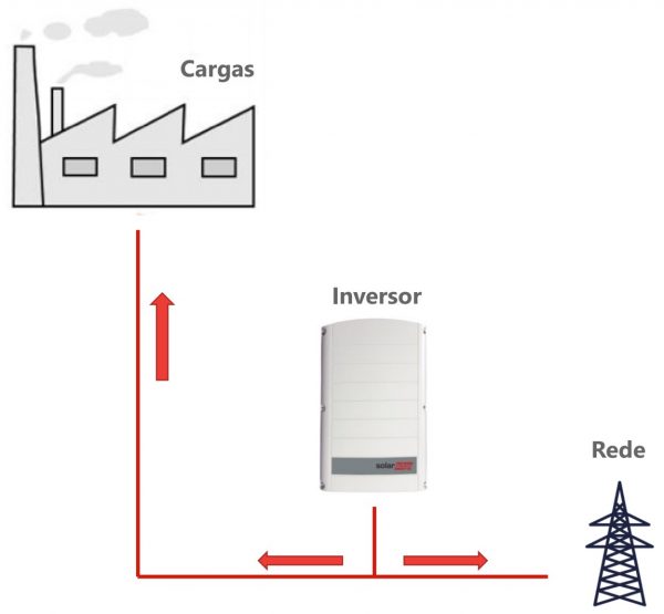
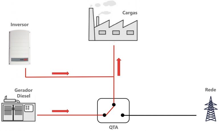
Figure 2 illustrates the situation that normally occurs in consumers who have diesel generation as backup or for use at peak times and wish to add photovoltaic generation.
The photovoltaic system in these cases is added before the automatic transfer board (QTA). The function of this panel is to interlock between the public electrical network and the diesel generator, in addition to automatically changing the position of the switch, transferring the diesel source to the consumer loads when the electrical network is absent.
In this type of configuration, the photovoltaic system only operates while the electrical grid is present. In case of failure, when diesel generation comes into operation, the photovoltaic system is switched off.
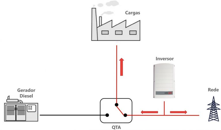
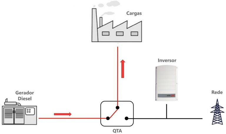
Figures 2 and 3 illustrate how QTA works. In figure 1 the electrical network is present and the key is in the position corresponding to the use of the network. Figure 3 illustrates the situation in which the network fails and the load power is transferred to the diesel generator. In the latter case, the electrical grid and the photovoltaic system are completely disconnected from the installation.
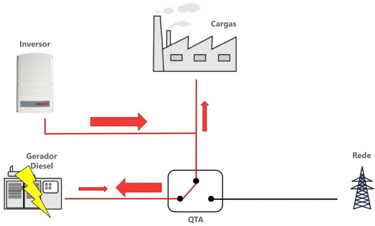
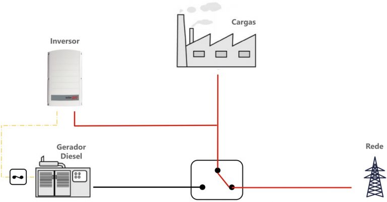
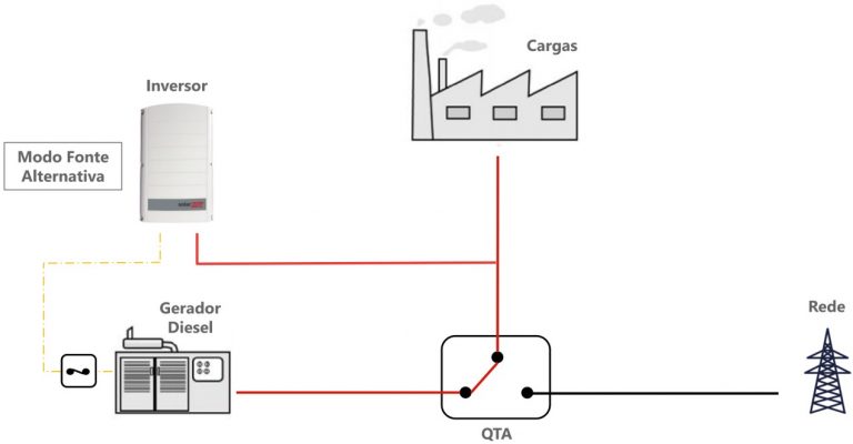
Figures 4 and 5 illustrate another possibility for connecting photovoltaic systems to consumers equipped with diesel generation. Note that in this case the inverter is connected after the QTA.
If the public supply fails, the inverter will stop operating in parallel with the grid and will start operating in parallel with the diesel generator – this last situation is illustrated in Figure 5.
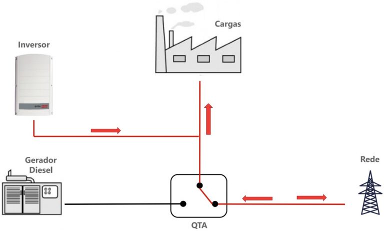
Connecting the photovoltaic system after the QTA can have two main advantages. The first, very simple, is to allow the connection of the photovoltaic system at any point in the installation, without the need for connection before the QTA.
This can allow, for example, a photovoltaic system to be connected to a consumer's internal distribution board, while the diesel generator is located further away, close to the entrance cabin.
In some situations, it may be costly to connect the photovoltaic system close to the input cabin and it is preferable to connect the inverters as close as possible to the consumer loads and also to the solar panels.
The second advantage of the connection strategy illustrated in Figures 4 and 5 (photovoltaic system after QTA) is that it allows the continued operation of the photovoltaic system even when the consumer is powered by the diesel generator.
The diesel source in this case simply replaces the electrical network, being responsible for the alternating voltage supply. The photovoltaic inverter connects to the diesel generator supply in the same way as it would be connected to the external electrical grid supply.
The obvious advantage of this connection mode is that it allows the use of photovoltaic energy, saving fuel. In addition to savings, this allows the system to increase its autonomy.
The combination seems perfect, but there are some complications with this type of connection. Firstly, if we want the photovoltaic system to operate in parallel with the diesel generator, it will be necessary to change the inverter settings.
The quality of power supply from the external network and the quality of power supply from the diesel generator are different. The diesel generator can offer wider voltage and frequency variation ranges than those found in the public electricity grid. The inverter must then be correctly parameterized to operate in parallel with the generator, avoiding shutdown due to over/under-frequency or over/under-voltage.
The second problem encountered in the parallelism between the photovoltaic system and the diesel generator is the return of excess energy, a situation illustrated in Figure 6. Unlike the external electrical grid, the diesel generator is not capable of absorbing the excess energy from the photovoltaic system. This means that the power of solar generation can never be greater than the power of the load.
The combination of photovoltaic and diesel generation in parallel is not complicated, but it requires technological solutions to overcome the challenges mentioned above. In short, it is necessary to parameterize the inverter according to the source to which it connects (external grid or diesel) and prevent excess photovoltaic energy from occurring.
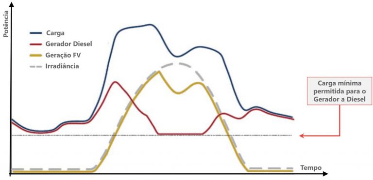
There is yet another concern when connecting a photovoltaic system in parallel with a diesel generator. It is necessary to respect the operational characteristics of the generator, always keeping it at a constant rotation and operating at a minimum power value. This is necessary to ensure good efficiency of the generator, in addition to extending its useful life.
Typically the minimum load of diesel generators is equivalent to 30% of their rated power. Low load diesel generators become inefficient and are subject to various phenomena that can damage them or considerably reduce their useful life.
Combustion engines are designed to always work as close as possible to their rated load and low load operation should be avoided.
So, even if solar generation is available and the entire load can be fed by the photovoltaic system, diesel generation cannot be reduced below a minimum value. This requires synchronization between the photovoltaic system and the diesel generator to eventually reduce solar generation when diesel generation reaches its lower threshold.
In short, for the reasons explained above, it will always be necessary to use at least 30% of the diesel generator's maximum power even if solar energy is available.
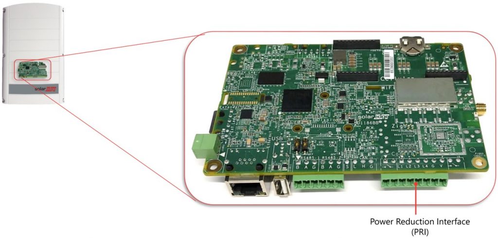
Below we will analyze three strategies that can be used in hybrid systems that combine a diesel generator and a photovoltaic system. In either case, the inverter must be equipped with a communication interface that has digital ports for signaling and/or RS 485 or equivalent communication interfaces, depending on the complexity of the control that will be carried out. Figure 8 illustrates the inverter communication module from the manufacturer SolarEdge.
Photovoltaic system disconnection mode
This is a simple function that can only be used to disconnect the photovoltaic system when diesel generation is active. In this case, the photovoltaic system is turned off and does not operate in parallel with the diesel generator.
This is not what we can exactly call a hybrid system, but this operating strategy could be useful for consumers who use diesel only for backup or at short intervals of the day – for example, during peak hours – and at the same time wish to have the photovoltaic system installed after the QTA.
In other words, diesel and solar sources share the same AC bus, but they never operate simultaneously. The generator is activated few times and for short periods of time and the loads can be met entirely by diesel generation, making it possible to dispense with photovoltaic generation in these short periods of time.
Why not let the photovoltaic system operate in parallel with the diesel generator? The answer is that the customer does not want to add this complexity to their installation and can do without solar generation in the rare moments when the diesel generator is activated.
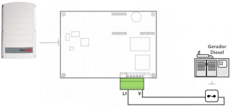
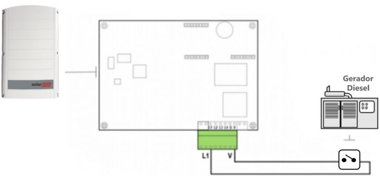
This operating strategy can be implemented, taking an inverter from the manufacturer SolarEdge as an example, by connecting a normal closed (NC) switch to the inverter's communication board.
The inverter must be equipped with a communication module and must have a communication input called power reduction interface (PRI). This is illustrated in Figure 9.

The photovoltaic system disconnection mode is a simple control method that allows the inverter to signal the presence or absence of the diesel generator, creating an interlock between these two sources.
This avoids the need to install the PV system before the QTA, making it possible to place it close to the loads or even close to the diesel generator. It's a detail that seems simple, but can have an impact on the cost of the electrical installation required to connect the photovoltaic system.
The function of this operating mode is only to turn off the photovoltaic system when the diesel generator starts operating, without any type of more sophisticated control. Naturally, in this case PV generation and diesel generation will never occur simultaneously.
This mode of operation is recommended in applications where the diesel generator is used only for backup and is not activated very frequently.
In this situation, the addition of a more complex system to control the photovoltaic system would not be justified, considering that the diesel generator is capable of supplying the entire load during a power outage – and this occurs for a short period of time. .
When the power outage ends, with the restoration of power from the public electricity grid, the diesel generator turns off and the signaling contact is closed, allowing the photovoltaic system to be reconnected.
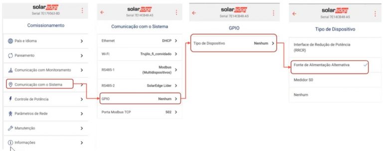
Figure 12 illustrates how the inverter must be parameterized to work in this mode. A general purpose I/O port (GPIO) must be configured to receive the contacts of a relay with an NC type switch. The system understands that the inverter can operate when the GPIO port is at a low level (relay contact closed) and understands that the inverter must turn off when the GPIO is at a high level (relay switch open) – as illustrated in Figures 10 and 11.
Operation mode in parallel with the diesel generator
In this operating mode, it is possible to simultaneously supply the consumer loads by the diesel generator and the solar source. Again, as in the previous case, a signaling relay is connected to the GPIO port. In this case, however, a normal open contact (NO) is used, as shown in Figure 13.
The main difference between this mode of operation and the previous one is that the photovoltaic system will always be in operation, either in parallel with the electrical grid or in parallel with the diesel generator.
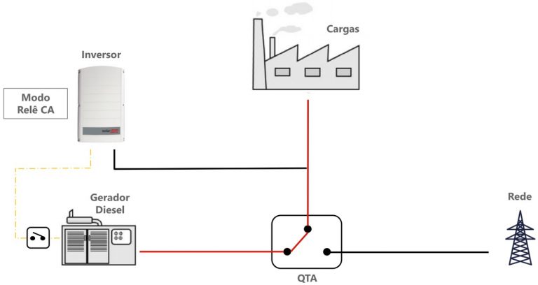
As shown in Figure 13, the connection diagram for generator parallelism mode employs a normal open contact (NO) on the diesel generator panel. The contact is open when AC grid is present and the generator is off, signaling to the inverter that it should operate normally in grid connection mode, like any other grid-tie inverter.
When the public network is turned off, the contact is closed, signaling to the inverter that it will now operate in parallel with the diesel generator.
In this case, the diesel generator will be the main source of power, replacing the electrical grid. The photovoltaic inverter must follow the generator voltage reference and be prepared to operate synchronously.
In short, with the key in the closed position, the inverter will understand that it is no longer operating with the utility's electrical network and needs to change its behavior to operate in parallel with the diesel generator.
In this case, the diesel-solar system constitutes what we call a microgrid, which is an autonomous network that operates in an islanded manner, disconnected from the public electricity grid, with its own energy sources.
For the inverter to be able to operate in this mode with two options (connected to the grid or connected to the diesel generator) it is necessary to parameterize it so that it understands the signals received at the GPIO port and mainly so that the inverter changes its behavior accordingly. with the main source present (mains or generator).
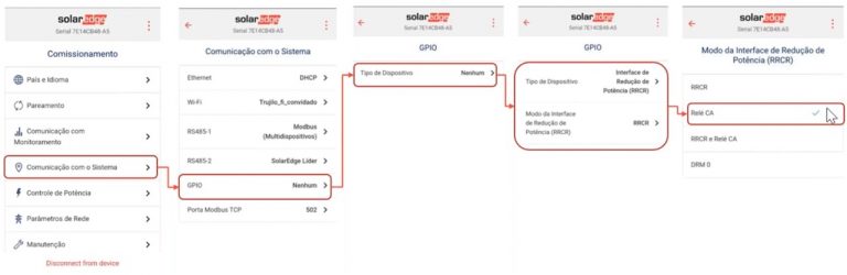
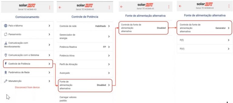
Figure 15 shows how the SolarEdge inverter GPIO port is configured to understand the relay signals with NO switch in this operating mode.
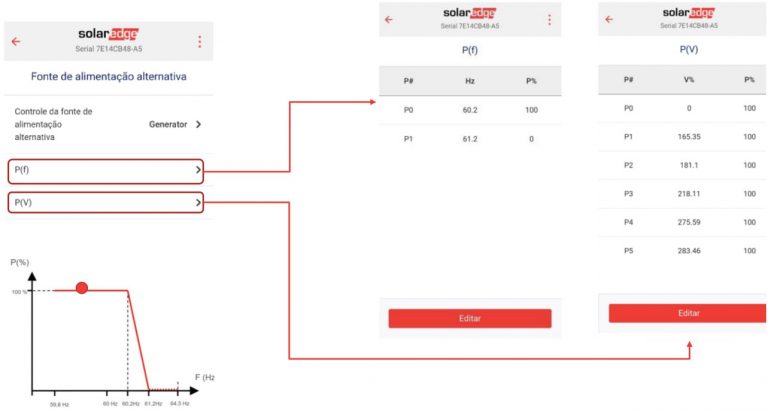
Next, we configure the power control modes, as shown in Figures 16 and 17. There are two modes that can be used: power x frequency or power x voltage. These operating modes are already pre-configured in the inverter, but can be parameterized according to each application.
The power x frequency control mode is most recommended when operating the inverter in parallel with a rotating machine. Rotating machines have their rotation frequency changed depending on the load. The increase in the power consumed by the generator causes its output frequency to decrease. Conversely, reducing power causes an increase in frequency.
This natural behavior of the generator can be used as a control signal for the inverter. The decrease in frequency signals that the generator is heavily loaded, therefore it is desirable to have solar generation to reduce the load on the generator.
On the other hand, the increase in frequency signals that there is excess power in the system and the generator works with little load, indicating that the power of the photovoltaic system must be reduced in order to avoid excess energy in the system, which cannot be absorbed by the generator.
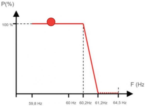
The power x frequency control strategy can be understood through the P x F curve. This generation curve is followed by the inverter when this operating mode is selected. As seen in Figure 18, for frequencies up to 60.2 Hz the photovoltaic system can generate 100% of its power.
When the frequency increases above 60.2 Hz, signaling that there is excess energy in the system, the power of the photovoltaic inverter will be gradually reduced until the system frequency reaches 61.2 Hz, when the inverter power will be zero.
Larger solar-diesel systems
The P x F control system shown above works well in small microgrids, typically with a few inverters operating in parallel with just one diesel generator.
In larger and higher power systems, when there are multiple diesel generators or multiple inverters, the power control solution through frequency variation may not present the necessary robustness to offer maximum reliability to the system operation.
In cases like this, it is recommended to have a system called power plant controller (PPC) – power plant controller.
This controller can have many functions, but in this specific case of solar-diesel integration it basically reads the power consumed by the load and regulates the generation of the PV system through communication lines. The big difference in relation to power x frequency control is that there is direct communication to send command signals from the PCC to the inverters.
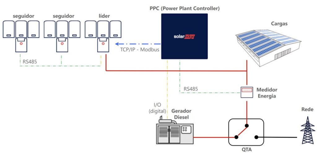
The way PPC talks to drives can vary from one manufacturer to another. Taking the SolarEdge solution as an example, a “leader” inverter communicates directly with the PPC, while the other “follower” inverters communicate with the “leader” to receive instructions.
PPC is the brain of the system. It ensures that diesel generation never falls below the generator's lower power threshold (typically around 30% of rated power, as previously mentioned).
The inverters will receive command signals to reduce their output power whenever there is a reduction in the power consumed by the load and the minimum power of the diesel generator has been reached.
With the use of plant controllers (PPC), it is possible to create large-capacity solar-diesel hybrid systems, capable of supplying consumers of any size in an islanded manner – disconnected from any public electricity grid: industrial plants, mining plants, rural properties or even a small town.


6 Responses
Hello, I am finalizing a PV System, Grid-Zero, managed by a Huawei smartlogger, where there is a Diesel generator connected right after the primary cabin.
I have doubts regarding priority delivery of the cargo.
Will the PV always provide 100% of its available power? How will the Generator behave?
There is no synchronization between the FV and the GD.
Excellent article!
Would you like to know which international standard this application is based on?
Do you have material or flyers for applications with higher generator powers?
I would like to receive more details about the larger solar-diesel systems (500 kVA) SolarEdge inverter
Can I integrate the generator with the inverter without the presence of the grid?
I have a case in Caldas Novas, the client has no network, has an expense of 100 thousand and wanted to reduce it with solar energy.
Can I get a system like this?
Good morning.
Which other inverters allow commissioning adjustment on a combustion generator?
Thanks.
Excellent teaching material