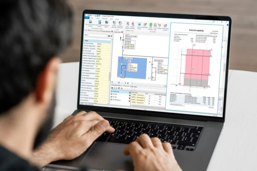
Ampere Evolution and the new software for calculation in electrical networks from the Electro Graphics. The software offers advanced tools for studying large-scale systems powered by renewable sources, such as solar and wind energy.
For these situations, it is essential to study of the effects of the longitudinal elements It is transverse of the network in calculating the Load Flow and the Curves in Capability, ensuring more complete and accurate analyses.
Furthermore, it develops specific models for wind generators and automatic reactive power compensation systems, allowing accurate simulation of different operating scenarios.
The software also has a innovative tool to the guided creation in photovoltaic systems. This tool simplifies the design process, allowing the automatic and controlled choice of photovoltaic modules, correlation with inverters and definition of system connection cables.
Ampere Evolution is a important advance in the calculation of electrical networks with distributed generationThe. The software considerably expands project possibilities, covering scenarios with renewable sources and paving the way for the implementation of intelligent networks (Smart Grids).
With Ampère Evolution, Electro Graphics reaffirms its commitment to innovation and technology. The software is a essential tool for designers who seek efficient and reliable solutions for the design of electrical networks, meeting market demands and driving the evolution of the electrical sector.

Connection of wind and photovoltaic systems
The management of wind and photovoltaic systems requires compliance with specific requirements from the energy distributor, related to the active and reactive powers available at the connection point.
Specifically, the overexcited reactive power varies according to a curve, from 35% Pnd to a minimum of 20% Pnd when the active power is equal to Pnd. As illustrated in the figure, a safe range of reactive power must be guaranteed, as the active power supplied to the grid varies.
Adjusting the operating points of generators or inverters may be insufficient to guarantee Pnd's 20% unless the rated power is increased, which is not ideal.
Automatic power factor correction systems can be used to balance excess capacitive power at low load or provide capacitive power at high load when lines absorb inductive power due to high currents.
This use, however, must comply with specific rules, and the Ampère Evolution software implements what is defined in Annexes A.17 and A.68 of Terna, which we report below.
Within the red and gray areas indicated in the figure, adjustments through the insertion/disconnection of static compensation elements are excluded, with the exception of the two cases described below.
- Above an active power limit agreed between Terna and the Customer at the level of the Operating Regulations (PdisconnectionRS), the disconnection of the shunt compensation reactors from the plant's MV network (if present) may be envisaged, recovering reactive control areas ;
- In the case of the presence of capacitor banks (if requested by Terna) these must be inserted above an active power limit (BC Insertion) and below a certain voltage (BC Insertion) agreed between Terna and the User at the level of Regulation Operational to partially compensate residual inductive losses as indicated by the blue filled area in the figure.
It is necessary that through this compensation a value of capacitive reactive power produced of 35% Pnd for active power values Pnd is guaranteed, with a minimum precision of ±2% Pnd in Vn.
With what has been defined, the Ampère Evolution software allows you to define Capacitor Bank type users and Shunt Reactor type users with a fixed insertion or disconnection value in relation to the active power measured at the connection point.

Let's see an application case below: the following figure represents a project created with three reactive compensation elements, a Shunt Reactor and two Capacitor Banks.
The power supplied at the source is approximately 2,030 kW, and consequently the project is working with the Shunt Reactor turned off, as the disconnection power of 700 kW has already been exceeded.
The first Capacitor Bank is active, with an insertion power of 1,800 kW. The second Capacitor Bank is still turned off and will be activated if the active power supplied exceeds the limit of 2,400 kW.
To put it simply, the three users bring Q reactive powers of 100 kVAR into play, providing the necessary steps to contain the reactive power within the limits of 20% and 35% required by the power distributor.

Capacitors bank
Capacitor Banks are managed by Ampère Evolution software as a variant of capacitive users.
In particular, to meet the requirements of the annexes described previously, the Capacitor Banks have an active insertion power, which commands the closing of the bank protection when this limit is exceeded and the disconnection if the active power absorbed at the supply level returns to a lower value.
Furthermore, these capacities cannot be adjusted, as they are a single bank with fixed reactive power. The designer can create several similar users with different but independent reactive power and insertion power values.
In the real case we will proceed as follows.
- Open or create a capacitive user.
- Access the User Properties dialog box using the […] button next to capacity.
- Select Capacitor Bank Capability from the Type drop-down list.
In electrical components, define the size of the capacitors, and in parallel how many microfarads are needed for the nominal working voltage.
Then, define the BC insertion power, a value that is compared with the active power provided by the distributor.
The software simulates the presence of an energy meter positioned at the delivery point (power supply to which the capacitor bank is electrically connected), whose operating logic activates or deactivates the user.
To deactivate the capacitor bank, enter a high value (greater than the maximum output power): this is the only way to freeze the user and completely deactivate it.
Among the configurable data is also the BC power hysteresis, the effect of which is only seen at a graphical level in the Capability Curve representation.


Note. Capacitor Bank users are highlighted in the grid using the Capability Curve symbol, which helps identify their specific functionality. It should also be noted that these users can only be activated or deactivated by software, the designer must impose a high limit to never have the capacitors connected to the network.
Furthermore, we remember that the work mode that considers the network elements must be active, which is essential to activate all the advanced functionalities dedicated to the study of wind and photovoltaic systems provided by Ampère Evolution (see the Network Elements tab of the window Properties).

Shunt reactors
Shunt Reactors are managed by Ampère Evolution software as a variant of inductive users.
In particular, to meet the requirements of the annexes described above, they have an Active Power Disconnect, which commands the opening of the reactor protection when this limit is exceeded and the activation if the active power absorbed at the supply level returns to a lower value.
Furthermore, these inductors cannot be adjusted, therefore they are a single shunt reactor with fixed reactive power. The designer can create several similar users with different but independent reactive power and insertion power values.
In the real case we will proceed as follows.
- Open or create a Shunt Reactor type user.
- Access the User Properties dialog box using the […] button next to Inductance.
- Select Reactor Shunt Capability from the Type drop-down list.


In electrical components, it defines the size of the reactor, and in parallel how many millihenrys are needed for the nominal working voltage.
Then, define the RS disconnection power, a value that is compared with the active power provided by the distributor.
The software simulates the presence of an energy meter positioned at the delivery point (power supply to which the shunt reactor is electrically connected), whose operating logic activates or deactivates the user.
To disable the shunt reactor, enter a value of zero; This is the only way to “freeze” the user and completely deactivate them. Among the data is also the RS power hysteresis, the effect of which is only seen graphically in the representation of the Capability Curve.
Note. Shunt Reactor type users are highlighted in mesh with the Capability Curve symbol, which helps identify their specific functionality. It should be noted that these users can only be activated or deactivated by the software; the designer must impose a zero limit to never connect the reactors to the grid.
Furthermore, we remember that the work mode that considers the network elements must be active, which is essential to activate all the advanced functionalities dedicated to the study of wind and photovoltaic systems provided by Ampère Evolution (see the Network Elements tab of the window Properties).
wind generators
The software allows the creation of three types of wind generators using the electrical model as the definitions reported in the CEI EN 60909-0 standard. The models allow the calculation of short-circuit currents of asynchronous generators, asynchronous generators with double fed power supply, and generators with full size converters.
For double fed generators, current values refer to the upstream terminals of the transformer, as the generator and transformer are considered a single unit.
Likewise, for the generator with a full size converter, the values must be understood upstream of the converter.
Double fed and full size converter generators allow adjustment of reactive power and support of fault currents, as frequently required by grid connection standards. KT correction factors are not applied to wind generators.

asynchronous wind
The ZG impedance of the asynchronous generator is calculated with the formula:
Where
- UrG is the nominal voltage of the generator;
- SrG is the apparent power of the generator;
- ILR/IrG is the ratio between the blocked rotor current and the generator rated current.
The software allows you to assign RG based on the XG, and if this information is not known, apply RG/XG = 0.1.


Double fed wind
The total direct sequence impedance ZWD of a station with an asynchronous wind generator with doubly fed power is calculated with the formula:

Where
- UrTHV is the nominal transformer primary voltage;
- kWD is the peak current calculation factor, provided by the manufacturer and referring to the primary side of the unit;
- iWDmax is maximum three-phase short circuit current.
If the kWD is not known, you can use the value kWD = 1.7.
The software allows you to assign RWD as a function of XWD and, if this information is not known, RWD/XWD = 0.1 applies.

Wind converter full size
The impedance depends on the type of converter, and for software it is assumed that it is the same as that used for storage systems. So the formula is as shown below:
Fault current support must be enabled in the generator parameters in the User Properties dialog box.

Composition of the photovoltaic system
Ampère Evolution provides guided sizing of the Photovoltaic System in the Tools tab of the command bar for creating a photovoltaic system, defining the composition of the field of photovoltaic modules, inverters and connection cables.
To start the photovoltaic system composition command, it is necessary to choose a distribution user to connect the system to.
The interface is made up of three pages that must be filled in sequentially:
- Components: definition of the power to be installed, choice of photovoltaic module and automatic search for inverters;
- Checks: reports the result of electrical coherence checks in the defined system configuration;
- Cables: definition of cables and connection sections of the photovoltaic system in DC and AC.
For more details, see the Ampère reference guide in the chapter “Networks with photovoltaic systems”.

Note. The “Photovoltaic system composition” function does not perform productivity calculations.

The opinions and information expressed are the sole responsibility of the author and do not necessarily represent the official position of Canal Solar.