
One of the main novelties of SOLergo 2022 Electro Graphics presented at Intersolar South America 2021 was the development of the layout of photovoltaic modules for a 3D photovoltaic project.
The generation of a 3D model allows you to optimally define the exposures and surfaces to be associated with the installation of photovoltaic modules.
According to the company, with the new SOLergo 3D layout tool, several functionalities are possible. Among them, the preparation of the 3D model of the installation location, arrangement of the modules in the presence of the 3D layout and calculation of losses due to shading.
See how to use each of the functions.
Preparation of the 3D model of the installation site
Within the SOLergo Exhibition window, the 3D Layout button opens the window in which it is possible to model the buildings and include the areas for installing the photovoltaic modules, by importing satellite images from Google, images photographed with a Drone or other devices.
Preliminary analysis of shadow areas
With the Draw shadow profile option, it is possible to carry out some simulations to project the shape of the shadow of obstacles onto the surfaces indicated as the module installation area.


The dialog box allows you to indicate the day of analysis and the density of the analysis points, as well as limit the shadow only in orientation to solar noon or identify areas with lower shadows, also corresponding to the moments immediately closest to each other. .
Arrangement of modules in the presence of 3D Layout
With the 3D layout design, it is possible to proceed with the arrangement of the photovoltaic modules with the help of automatic positioning. The positioning of the photovoltaic modules within the installation areas occurs in the 3D plane and each element will be positioned within the exhibition to which it belongs.
After completing the module insertion phase in automatic or manual mode, it is possible to obtain a 3D view of the entire system by starting the 3D Layout command, available in the toolbar
Calculation of losses due to shading
Within the 3D Layout window, the user can also simulate shading from nearby obstacles and view the results of losses each month.
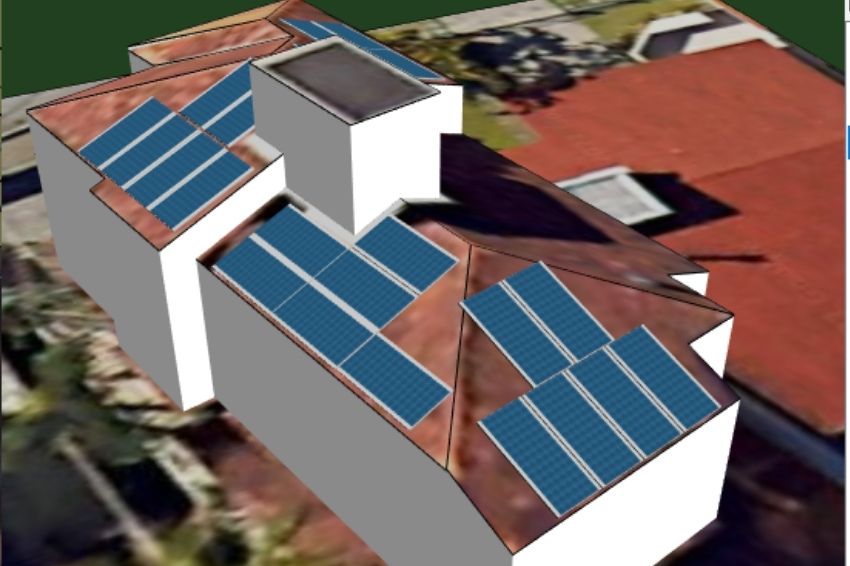
3D model image creation
Once the entire Layout design, arrangement of modules and shading analysis have been completed, the user can also capture images of the Layout in 3D to display in the project documentation.
With SOLergo 2022, it is possible to obtain the 3D model in a simple and effective way, aiming to obtain an accurate energy analysis and a photorealistic representation of the built system.


One Response
To have contact