
Everyone knows the importance of grounding and equipotentialization for the safety of equipment and people. However, projects often contain serious flaws that end up compromising the integrity and functionality of the grounding system.
Given this scenario, equipment in this segment of the photovoltaic sector is evolving towards practicality, to make what used to be complex simpler, requiring too much labor and resulting in longer and more expensive projects. In this article we will present some solutions for grounding and equipotentialization.
The equipotentialization and grounding of photovoltaic modules and structures involves these challenges:
- Interconnection of module frames, making them equipotential;
- Connection of modules to the structure, making them equipotential;
- Connection of the set of modules and structures to the grounding grid.
Interconnection of module frames for equipotentialization
This task can be done using external conductors, properly connected to the frames of the photovoltaic modules, or using more advanced devices, which reduce working time.
Conventional solution
The conventionally used solution is the “grounding pigtail”, which is a cable with eye-type terminals at its ends, as shown in the following figure. The ends of the pigtail are connected to the grounding holes of the photovoltaic modules by screws and nuts.
This solution, in addition to requiring time and effort, has traditionally not been identified as the best option for the equipotentialization of photovoltaic modules. Screws can become loose or, when using unsuitable materials, the screws end up oxidizing and deteriorating quickly, as seen in many photovoltaic installations.
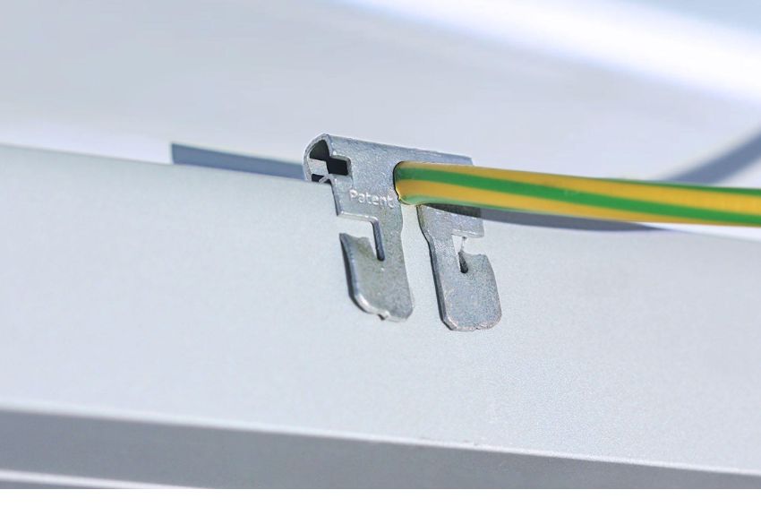
Rayvolt Solution – ARaymond
This solution consists of the use of special clips, which are easy to attach, which optimize the time spent during installation and provide long-lasting, failure-free electrical contact. The risks of poor connection and equipotential failure are then eliminated.
Equipotential conductors are connected to the frames of one module after another, without the need for crimping pliers, screws or nuts.
This new way of grounding and equipotentialization of structures, in addition to reducing the equipment needed to carry it out, also reduces labor for installation, consequently reducing assembly time, which provides a considerable advantage in the construction of solar plants.


Ground clip solution
This alternative solution eliminates the use of cables or pigtails, making the modules equipotential through a metal clip positioned between the fixing structure and the module frame. The idea is to ensure that the module frames are electrically connected to each other and also to the fixing rails using clips. Thus, modules and structures are equipotentialized without the use of electrical cables.
With this solution it is possible to reduce installation time and consequently reduce the cost of the work, due to savings in materials and labor. Manufacturers such as PHB Solar, 2P and SSM, among others, provide solutions of this type.
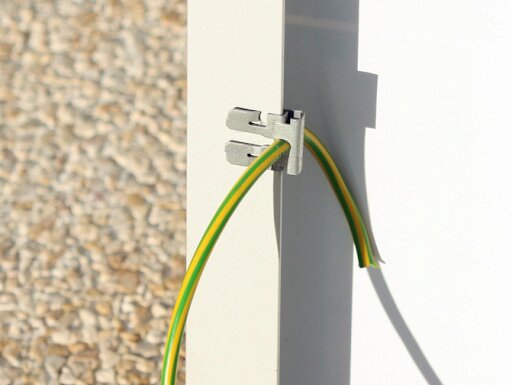
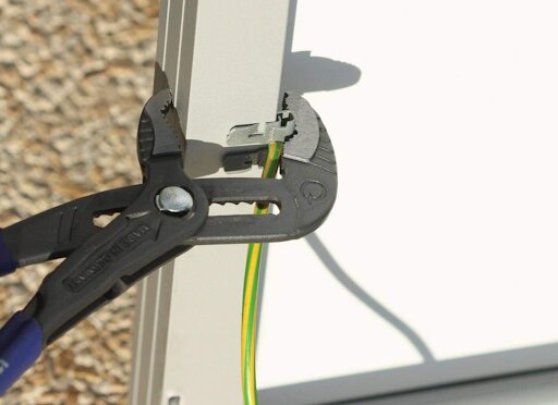
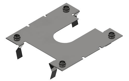
The following figure illustrates a PHB grounding clip. The device has four protruding points on the top and bottom faces. These protruding points penetrate the surfaces of the module frames and break the anodizing layer, ensuring electrical contact.
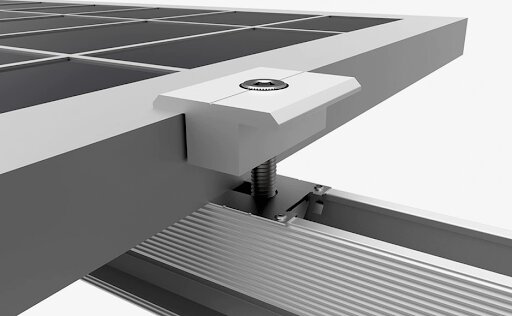
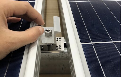
The following two figures illustrate how to install the grounding clip. In both examples we see one end of the clip pressed between the frame of a module and the fixing rail.
Equipotentialization between structures and the grounding grid
Equipotentialization between structures can be done by grounding clamps that fit into the fixing rails of the photovoltaic modules and cables, as shown in the following figure. The same solution can be used to make the connection between the structures and the installation's grounding grid.
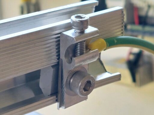
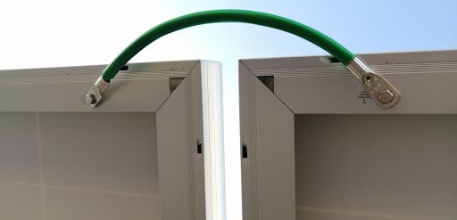
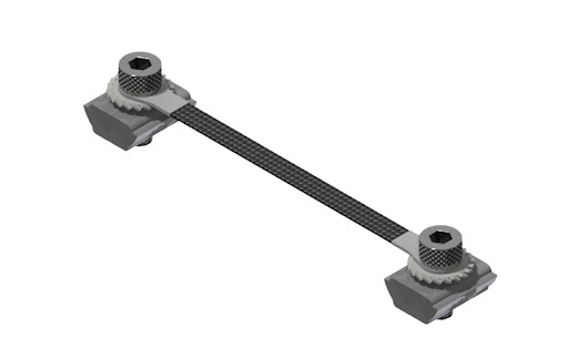
In the PHB solution, equipotentialization between structures can be carried out using special jumpers, avoiding the need to use cables, as shown in the following figure. The manufacturer's recommendation is to install the jumper between the seams of the metal fixing profiles.
Final considerations
The solutions presented provide practicality, accessibility and cost reduction. It is worth noting that all recommendations indicated in the installation manuals must be respected, in order to guarantee the effectiveness of the products.
Furthermore, continuity tests must be carried out to verify whether the structures are in fact equipotential. It is also important to remember that the module installation manuals must be checked to ensure that the solutions are compatible with the module manufacturers' recommendations, to avoid voiding the warranty.


One Response
good morning,
Is it viable and technically correct to use insulated aluminum cables (material used in external/weather overhead lines) to interconnect the grounding between modules + inverter + grounding equalization bar + grounding mesh?
The purpose of using this type of aluminum cable is in relation to the useful life of this type of cable, which is “special” for working over time.