Photovoltaic systems can be used in a wide variety of locations such as large cities, coastal regions, farms, rivers, forests, deserts or even in space. Each of these locations requires that the equipment used has special characteristics, ensuring its proper functioning throughout its operation. This article will address studies related to the effects of salinity present in coastal regions on photovoltaic modules, in addition to presenting the salt spray test, which is one of the evaluation procedures that can be carried out on photovoltaic modules to ensure their quality and durability. Photovoltaic modules are developed to withstand the most diverse environmental conditions, whether wind, rain, snow, hail, sea air, ultraviolet radiation or even the ammonia present in the air. Aiming at certification according to compliance standards, the IEC (International Electrotechnical Commision) proposes in the IEC 61215 standard, a sequence of tests that determine the electrical, thermal and mechanical characteristics of a photovoltaic module. As it is a standard that covers several qualification tests for photovoltaic modules, it has become a reference for the INMETRO Ordinance 004/2011 (National Institute of Metrology, Quality and Technology), which regulates the certification of photovoltaic modules in our territory. Although INMETRO's compulsory certification requires only a small part of the requirements of the IEC 61215 standard, manufacturers themselves request more specific tests from large testing laboratories, being able to acquire quality seals of different levels – such as, for example, the TÜV certification seal, which includes all the tests described in the IEC standard. In Brazil, there are some initiatives to carry out complementary tests to those required by INMETRO. The LESF (Energy and Photovoltaic Systems Laboratory) at UNICAMP (State University of Campinas), for example, will be expected to carry out from 2021 onwards a large part of the procedures listed in the IEC 61215 and complementary standards, providing an additional quality reference for photovoltaic modules sold on the national market. As it is a standard that contains the main tests that characterize a photovoltaic module, IEC 61215 is commonly cited in other standards that govern different operating conditions of photovoltaic modules. As the scope of this article is focused on the effects of salinity on photovoltaic modules, discussions will be presented on IEC 60068-2-52 (standard for environmental testing with photovoltaic modules, which defines tests under dry, humid and saline conditions) , in addition to IEC 61701 (standard for testing corrosion of photovoltaic modules due to salt spray). Because this article revolves around the effect of salinity on photovoltaic modules in accordance with the aforementioned standards, salt spray test procedures will also be demonstrated.
Salt spray test motivation
In photovoltaic installations close to coastal regions, there is great concern about a phenomenon called salt spray, popularly known as salt air. This effect occurs due to the fact that sea waves, when breaking on the coast, release a spray with saline content, causing salt particles to become dispersed in the air. The spread of sea spray in the air depends on several factors, such as: concentration of sea salt in the oceans, relative air humidity, wind propagation in the region, ambient temperature, in addition to nearby civil constructions. Due to the various factors presented, the spread of salt spray has a completely different pattern from one location to another. According to the ocean salinity map, different salt concentrations can be noted, demonstrating that the effect of salt fog can present itself with different levels of intensity in the most diverse locations in the world. The Brazilian coast, for example, is one of the regions with the highest levels of salinity in the world.

A study carried out in Rio de Janeiro analyzed the reach of sea spray from the sea that bathes Copacabana beach. In this study, the result was the presence of sea salts at a distance of 7 km from the coast, demonstrating that the effects of salinity must be considered, even if the installation is relatively far from the sea. Due to the inherent corrosive effect of salt spray on metallic elements, it remains to be seen how photovoltaic modules behave in the face of this natural phenomenon. The salt spray test involves three different standards, namely: IEC 61701, IEC 61215 and IEC 60068-2-52. To carry it out, two samples of the same model are required to carry out the test cycle.
Preparatory procedures
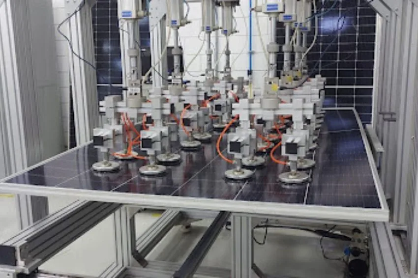
Given the fact that the salt spray test is an activity that causes damage to the photovoltaic module, the IEC 61701 standard defines a series of tests that must be carried out before and after the salt spray test, in order to qualitatively elucidate the effects of the test. . The tests prior to the salt spray test are as follows:
- Preconditioning with ultraviolet (UV) light, in which the module is exposed to ultraviolet radiation of at least 5 kWh/m2;
- Visual inspection to detect any imperfections or degradation in the module.;
- Flash test to determine the main electrical characteristics such as Isc (short circuit current), Voc (open circuit voltage), Pmp (maximum power);
- Insulation resistance test;
- Leakage current test with humidity.
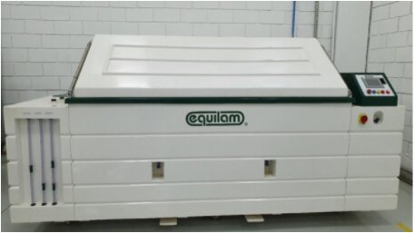
Salt spray chamber
Once the collection of preliminary data from the samples has been completed, the modules are prepared to perform the salt spray test. At this point, the IEC 60068-2-52 standard will be predominant in defining the testing requirements for the samples in question. This standard regulates 8 different salt spray tests, based on 3 different processes. For this reason, it is necessary to explain the main mechanisms that make up the salt spray chamber.

The chamber has a hydraulic connection with a source of deionized water, so that its solution tank can be filled with a liquid without minerals that could negatively affect the test. In this same tank, 100 liters of deionized water and 5 kg of high purity sodium chloride are mixed, composing the saline solution specified in accordance with IEC 60068-2-52. For this solution to effectively become a salt mist, the solution must pass through the saturation tower (internal component of the machine). In this tower, the solution is heated and pressurized using a compressor, reaching an ideal combination of temperature and pressure to transform the water into mist. The mist generated by the saturation tower is directed to the solution dispersion tower, allowing the saline spray to spread throughout the chamber. At the end of tests involving salt mist, the solution collection funnel captures particles dispersed in the air, transporting the particles back to the solution tank. The IEC 600682-52 standard mentions 8 different tests, based on four different processes that can occur in the chamber, in addition to explaining the intensity levels of each process, being the following processes:

- Salt fog process: In this process, the sample is exposed to a salt fog for 2 hours and a temperature of 35oC ± 2oC. The solution, when deposited on the surface of the sample, can create an electrolytic film, which can initiate the corrosion process;
- Process under dry conditions: In this process, the chamber operates at a temperature of 60oC ± 2oC and relative humidity of 30%, for 4 hours. The heated air causes the evaporation of water on the sample surface, increasing the concentration of salt particles on the sample surface, therefore accelerating the corrosion process;
- Humid condition process preceded by salt spray: In this process, the chamber operates for 22 consecutive hours at a temperature of 40 oC ± 2 oC, in addition to a relative humidity of 93% ± 3%. This operation of the equipment maintains the existing humidity on the surface of the module at the end of the salt spray process;
- Standard atmosphere process: In this last process that can be carried out by the chamber, the relative temperature and humidity are close to normal ambient conditions. This process allows the solution deposited on the sample to dry naturally, which can trigger different corrosive processes in the modules.
Based on these procedures, IEC60068-2-52 defines 8 different tests for different scopes of analysis, namely:
- Tests 1 and 2: Tests aimed at elements operating close to the ocean, being of high interest for modules installed on naval vessels or in coastal areas, whose period varies between 3 and 28 days;
- Tests 3 to 6: Tests aimed at elements that operate under intermittent salinity conditions, with test periods ranging from 7 to 56 days;
- Tests 7 and 8: Tests aimed at the automotive sector, whose period varies from 1 to 60 days.
Although these tests cannot perfectly portray a real salt spray situation, test 3 of IEC 60068-2-52 is the one that comes closest to the interaction of saline spray and photovoltaic module, in addition to having a satisfactory test period for it to be possible to carry out comparative analyzes of the effect on the samples.
IEC60068-2-52 Test Method 3
According to test 3 of the IEC 60068-2-52 standard, for 4 days the modules are subjected to 2 hours of salt spray and then subjected to humid conditions for 22 hours. The relative humidity of the chamber must be in the range of 90% to 96%, in addition to an internal temperature of 38oC to 42oC. Finally, the modules remain in the chamber for another 3 days under usual ambient conditions of 21oC to 25oC and relative humidity between 45% and 50%. The chamber test flowchart is shown in Figure 4.

Final procedures
Once the test cycle is complete, the module is carefully removed from the chamber and immediately sanitized with demineralized water, so that the saline residues are completely removed. Then, the module is subjected to a new sequence of tests, in order to compare with the results obtained prior to the test. The first test to be carried out is visual inspection. At this stage, traces of degradation are looked for in the test element, such as: corrosion of metal surfaces, MC4 connectors, bypass diodes and also internal solders. As the modules go through a thermal cycle, the internal welds end up being carefully evaluated, as the process of contraction and expansion of the welds occurs due to this thermal variation. In cases where the solder is of low quality, sudden temperature variations can cause irreversible damage to the connections and bring undesirable consequences such as a greater propensity for hotspots [3]. Faults can be detected visually, simply by checking whether the welds connecting the busbars are deformed, or demonstrating electrical discontinuities. The flash test is then carried out in order to analyze whether the electrical parameters were maintained or whether there was any significant degradation during the process. After this test, the element undergoes a leakage current test in humid conditions, aiming to compare the module's insulation resistance before and after the test. Finally, the module goes through an activation test of the bypass diodes. In this test, one of the cells is completely shaded with the help of a dark screen and then the module goes through the flash test again to check that the diode is working properly.
Approval Requirements
After carrying out the sequence of tests in the salt spray chamber, the following requirements must be observed for the approval or disapproval of the photovoltaic modules:
- Samples must undergo a rigorous visual inspection, described by the IEC 61730-2 standard, without showing mechanical deterioration or corrosion of the module components;
- The maximum power measured according to the flash test cannot be less than 5% with respect to the value measured before the test;
- Insulation resistances under dry and humid conditions must remain intact;
- The module's bypass diodes must remain intact.
Conclusion
Photovoltaic modules must undergo rigorous laboratory tests before it can be said with certainty that they are capable of withstanding the most diverse operating conditions. The salt spray test, which corresponds to subjecting the product to a salt spray environment, is an important qualification procedure for photovoltaic modules within the scope of analysis. The salt spray test is not required in Brazil, but several global manufacturers submit their products for certification in international laboratories. If the consumer needs to know whether the module is certified to operate in high salinity regions, it is recommended to consult the product data sheet or contact the distributor or the manufacturer itself.