Article published in the 11th edition of Canal Solar Magazine
Mechanical load tests are one of the requirements for international approval of photovoltaic modules in accordance with the IEC 61215 standard. In Brazil, this approval is not yet mandatory and the tests are not part of the list of tests required by the INMETRO (National Institute of Metrology, Quality and Technology).
However, the mechanical load testing have already been carried out (still as research) in LESF (Energy and Photovoltaic System Laboratory), built in a partnership between BYD Energy and UNICAMP, State University of Campinas.
Originally it was required, according to the standard IEC 61215, only the static mechanical load test, that is, with the application of constant pressure on the modules for a period of one hour – alternating between negative and positive pressure over three cycles.
The most recent version of the IEC 61215 standard (from 2021) included the dynamic load in the set of mandatory tests, which must be carried out in accordance with the procedures of the standard IEC 62782:2016, making the quality control of photovoltaic modules that aim to obtain international certification even stricter.
The main motivation for static mechanical load testing is related to a problem found in countries with cold climates: the snow that accumulates on the modules during winter.
Snow loading represents a significant problem for the integrity of photovoltaic modules. The weight of accumulated snow exerted on the photovoltaic modules can cause the cells to break and reduce their useful life.
In Brazil we do not have a problem related to snow, but in any case the static mechanical load test is a good parameter to check the mechanical resistance of the product. Many climatic effects, such as storms with rain and strong winds, cause concern about the durability of photovoltaic modules throughout their useful life.
The tightening of IEC 61215 requirements regarding mechanical load tests meets the need to test modules capable of withstanding different weather conditions without suffering severe damage or accelerated deterioration.
IEC testing examines the effect of uniform static or dynamic loads on photovoltaic modules, but does not consider non-uniform loads due to wind effects.
Although they are important as quality tests, currently existing regulatory procedures do not reproduce the complexity and intensity of the actions suffered by photovoltaic modules in real conditions.
There is also the challenge of improving mechanical load test procedures, especially for strong winds, in addition to understanding how different weather phenomena affect the integrity of components and reduce the useful life of photovoltaic modules.
Sample preparation
The photovoltaic module to be tested must be subjected to a preconditioning process, in accordance with IEC 61215-2. This pre-conditioning aims to stabilize the module's power, making it suffer the initial power degradation to which every crystalline module is subject in the first hours of use.
The procedure consists of leaving the module exposed to accumulated irradiation between 5 kWh/m2 and 5.5 kWh/m2, with natural or artificial light. The preconditioning time depends on the available irradiance, which may depend on weather conditions if the procedure is carried out in natural light.
Considering, for example, an average irradiance of 800 W/m2, the test should take around 7 hours to complete. Typically this test takes 1 to 2 days, if weather conditions are favorable.
Qualification and approval tests
Qualification tests are necessary to verify the health status of the module before and after mechanical tests.
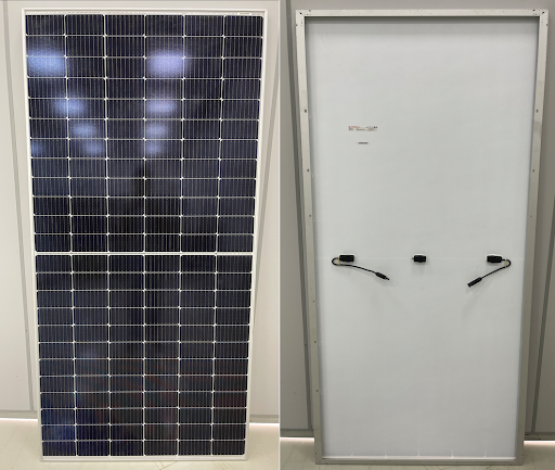
Test 1: Visual inspection
The objective of the visual inspection test is mainly to check manufacturing defects or damage occurring after mechanical tests. Normally, defects in cells and electrical connections cannot be noticed during this inspection.
What is looked for in this test are defects that could fail the module, preventing a module in poor condition from being tested. Furthermore, after carrying out the mechanical tests, it is necessary to check whether the module is still intact.
Visual inspection may reveal the existence of bubbles and delamination (detachment of the plastic material that surrounds the cells), cell misalignment, poorly made welds, defects and cracks in the glass, deformations in the frame, failed seals, damage to the junction box and cracks or scratches on the backsheet, for example.
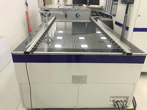
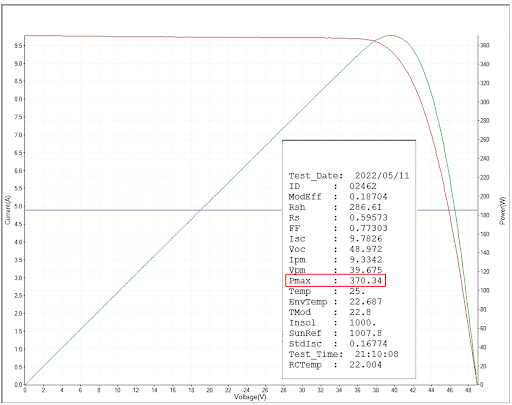
Test 2: Maximum power
The maximum power test is performed with a pulse of light. To do this, a machine capable of emitting a flash of light with the same characteristics as sunlight is used.
During the test, the IV curve (current and voltage) of the photovoltaic module in STC (standard test conditions) is obtained, from which the electrical parameters (peak power, open circuit voltage and short circuit current) are obtained. ).
The module will be considered approved in this test if, after undergoing mechanical tests, it has not suffered power degradation greater than 5%.
Test 3: Electrical insulation
The main objective of the electrical insulation test is to certify the safety of the module, checking whether it poses a risk of electric shock when in operation.
A photovoltaic module in good condition does not allow any contact by people with the internal components (cells, electrical conductors and other live parts). Furthermore, insulation testing is also used to check the extent of damage suffered by the module after undergoing certain tests.
A reduction in the electrical insulation resistance value is a strong indication of module deterioration, which may cause it to fail. In any situation, before or after mechanical tests, the electrical insulation resistance of the module cannot be less than 40 MΩ/m2 (resistance between the electrical terminals and the frame divided by the area of the photovoltaic module).
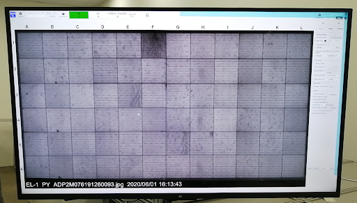
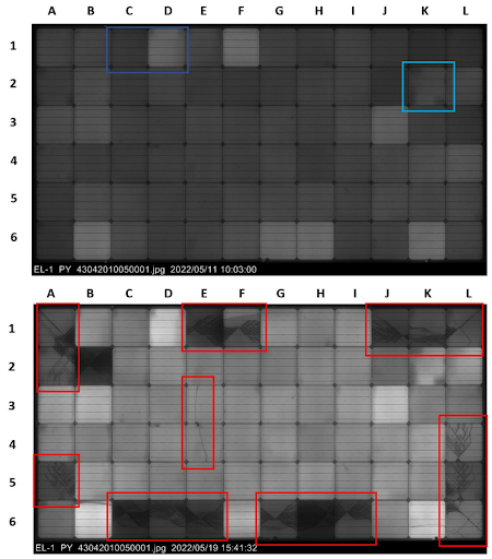
Test 4: Electroluminescence
Although the IEC 61215 standard does not require electroluminescence testing, this procedure is an important ally in checking for defects in photovoltaic cells and also in the cells' electrical interconnections.
In this test, the photovoltaic module is powered by an external energy source, functioning as a light-emitting diode. The glow emitted by photovoltaic cells is not visible to the human eye, but can be detected with a special camera.
The result of the electroluminescence test is an image that looks like an “X-ray”. The electroluminescence image reveals the existence of cracks and microcracks in the photovoltaic cells. There is no clear parameter to define a passing criterion for the electroluminescence test.
Ideally, it is expected that no cracks or microcracks will occur in the photovoltaic cells, but this is impossible. After the mechanical tests, some degree of cell deterioration will be noticed. The objective criterion for approval or failure is the verification of the module's output power, as well as the insulation resistance (tests 2 and 3).
The electroluminescence test can be useful to reveal a greater or lesser quantity of damaged cells, allowing to compare different installation modes, different models or manufacturers or different configurations (applied pressure, number of cycles, speed) for mechanical tests, among other things. .
Static Mechanical Load Testing Procedures
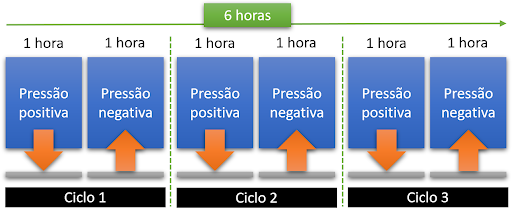
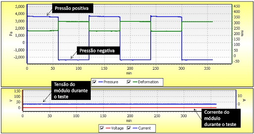
This test consists of applying positive and negative pressures of at least 2400 Pa on the surface of the module for a period of 1 hour for each pressure value.
The test has 3 cycles, each containing 1 hour of positive pressure application and 1 hour of negative voltage application. The total test lasts 6 hours.
Although the IEC 61215 standard requires a minimum pressure of 2400 Pa, many manufacturers specify their modules for higher pressure values, such as 3600 Pa, 4000 Pa or 5400 Pa.
Manufacturers define the positive and negative pressures supported by the modules according to the fixing method, as in the following example.
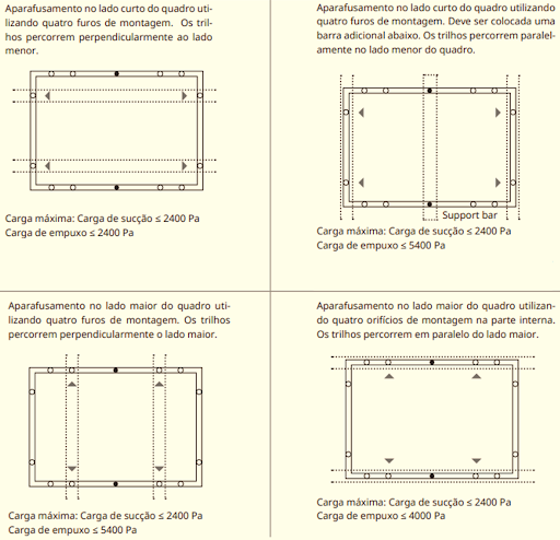
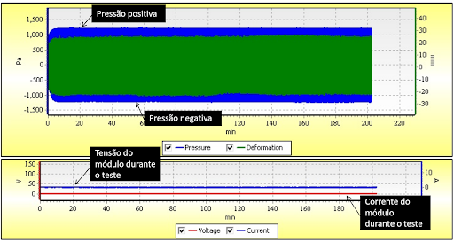
The test must be carried out in accordance with the values presented in the data sheet, in addition to the minimum values required by standard. During the test, a small electrical current must be applied through an external power source.
The module voltage must be kept close to its open circuit voltage. This serves to guarantee the electrical continuity of the module during mechanical tests. If the current is cut and there is a loss of continuity, this means that the module has been damaged and must be immediately rejected.
The static mechanical load test can be carried out in several ways, with the application of sandbags or columns of water with the module facing up and down (to apply positive and negative pressure in relation to the surface of the front glass).
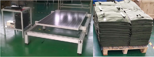
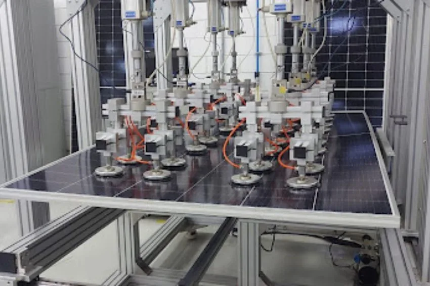
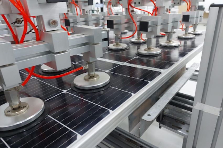
The most appropriate method, however, is the use of a mechanical load testing machine equipped with suction cups and pneumatic cylinders. Tests are only carried out with the module facing upwards. The suction cups stick to the glass surface, allowing positive pressure (pushing the module down) and negative pressure (pulling the module) to be applied.
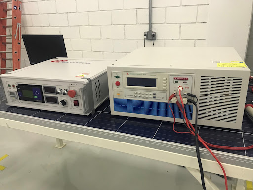
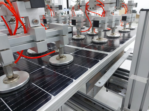
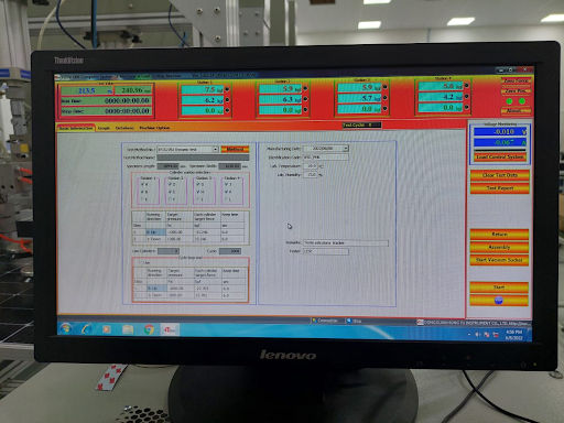
The control of the pneumatic cylinders allows you to precisely adjust the pressure exerted on the module, in addition to allowing tests with different pressure values, according to the configuration made by the user. The following figure illustrates a Hototech machine for mechanical load testing, model HTPV-08B.
Pressure and application time settings can be defined by the user. The accuracy of the applied pressure is 5%. The equipment has 12 cylinders, distributed in 4 groups, which move pneumatic suction cups that are attached to the surface of the photovoltaic module.
Dynamic Mechanical Load Testing Procedures
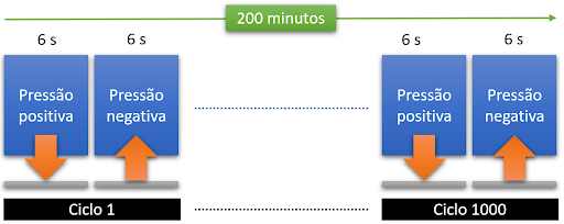
The dynamic (or cyclic) load test is carried out in accordance with the IEC 62782:2016 standard, with cycles consisting of the application of positive pressure of 1200 Pa (module being pressed) and negative pressure of -1200 Pa (module being pulled by suction cups).
1000 cycles are carried out with the application of positive and negative pressure, lasting 6 seconds for each application. In reality, what differs between static and dynamic load tests are the number of cycles, intensity (applied pressure) and speed.
Conclusions
Static and dynamic mechanical load tests aim to verify the module's supportability to mechanical stress. Originally the IEC 61215 standard only required static testing, the main motivation of which was to verify the module's ability to withstand snow loads in countries with cold climates. Recently, the IEC 61215 standard also began to require dynamic load testing, the procedure for which is described in another standard – IEC 62782.
* Article written in collaboration with Mendelsson Rainer, Thais Crestani and Eslam Mahmoudi
The opinions and information expressed are the sole responsibility of the author and do not necessarily represent the official position of Canal Solar.