
High temperatures cause operational problems and reduce the useful life of electronic equipment and systems.
In photovoltaic systems this situation is no different, with the aggravating factor that the equipment can often be exposed directly to the Sun.
Exposure to high temperatures is, in general, one of the main causes of problems with the efficiency and useful life of system components.
In photovoltaic modules, for example, the effect is due to the thermal behavior of the cell, reducing the system's energy generation capacity.
The problem is accentuated when it comes to the inverter, which in addition to the impact on its efficiency, will also have its useful life reduced.
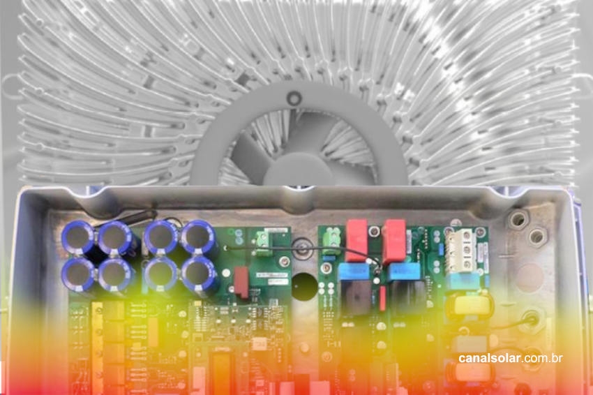
In inverters, heat is more difficult to control, as it tends to concentrate around the electronic transistors, which are a direct part of the energy conversion, in addition to the input capacitors (on the direct current side), which are one of the main causes of failure in electronic inverters.
For the inverter to remain within its ideal operating temperature, cooling techniques must be used. Usually, two cooling techniques are used: passive and active.
Understanding the problem
Among the effects of high temperature on inverters, power reduction due to temperature (temperature derating) is what most impacts the generation of the system.
Power reduction due to temperature occurs when the inverter reduces its output power in order to reduce heat generation in the transistors and other internal components. This is done to ensure that the operating limits of these components are respected.
The higher the ambient temperature, the greater the likelihood of energy losses due to power reduction. The figure below shows the behavior of an inverter's output power at different temperatures.

From the point of view of the inverter's useful life, the most vulnerable are the power electronic transistors and the DC bus input capacitors, generally electrolytic. Like all electronic components, their useful life is directly linked to the temperature at which they operate.
The capacitor, when exposed to extreme heat for prolonged periods, can be completely damaged, causing electrolytic material to leak.

The useful life of an electrolytic capacitor is temperature dependent according to the equation below.

Where:
- L – Life time corrected by temperature;
L0 – Planned useful life within the nominal temperature limit;
T0 – Nominal operating temperature;
Tx – Operating temperature analyzed.
From the equation we can see that increasing temperature causes an exponential decrease in useful life. The opposite is also true: if the capacitor works at a temperature lower than its nominal operating temperature, its useful life is prolonged. The EPCOS B32774 family capacitor, typical in photovoltaic inverters, has the useful life curve below.

The power electronic transistors used in inverters are typically of the IGBT type (insulated gate bipolar transistor), very suitable for this type of application due to its ability to withstand high voltages and currents, in addition to being able to operate at switching frequencies of a few tens of kilohertz (kHz).
Transistors, manufactured with silicon, participate directly in switching and are directly responsible for the process of converting direct to alternating current.
As IGBT transistors receive all the current generated by the inverter and operate in a switching regime, being subject to switching and conduction losses (the two types of losses that occur in transistors in switched converters), the power dissipated in them is high.
To reduce the effects of increased temperature during operation, IGBTs are equipped with a metallic part (on the back of their plastic casing) that is connected to the inverter's heat dissipation system.


In the figure below we see a 10 kW inverter from the manufacturer Fronius, which uses an active cooling solution, which helps to reduce derating and provides more efficient inverters with a smaller physical volume, as well as a longer useful life.

Excessive instantaneous temperature can melt the IGBT transistor. Silicon, the material from which the transistor is manufactured, has a temperature limit.
Furthermore, when working at high temperatures, like the capacitor and other components, the transistor acquires a shorter lifespan.
The MTBF (mean time between failure), mean time between failures, is a figure of merit widely used in the electronics industry to quantify the lifespan of components and equipment. The MTBF of transistors tends to decrease (shorter lifetime) as the temperature increases.
Good equipment manufacturers normally use transistors with specifications, that is, larger than those that would actually be necessary depending on the current and voltage specifications that the application requires.
This clearance, associated with a good thermal dissipation system, guarantees a long MTBF, which consequently provides safe and prolonged operation of the equipment.
The graph below shows the lifetime in hours for multiple operating voltages and temperatures for a manufacturer's IGBT transistor Infineon, suitable for photovoltaic inverters. Long-term excess temperature causes an exponential reduction in the component's useful life (just like in the electrolytic capacitor).

Inverter Cooling
One of the most commonly used ways to reduce the temperature of inverter components is to use fans. They increase the air flow that passes through the thermal fins, which increases the efficiency of heat exchange with the components.
The active cooling solution brings some benefits over passive ventilation. As heat transfer is greater when there is forced ventilation, the heat sinks in inverters with active cooling can be smaller, making the inverter lighter and therefore easier to install.

The active cooling fan speed is controlled based on the temperature measured internally to the inverter. When the inverter is not operating at higher powers, the passive heat sink may be sufficient to cool it to satisfactory levels.
Therefore, at these times the fans may reduce their rotation speed or even turn off completely. This fan rotation control also has the benefit of increasing its useful life.
A typical lifetime value for these fans is 80,000 hours of operation at full speed, which is equivalent to nine years of continuous operation. Taking into account the working regime in photovoltaic inverters, the useful life of the fan will be greater than 20 years.
Passive cooling requires air convection on the heatsinks, that is, the heatsink transfers heat to the air which, as it is now hotter, becomes less dense than the cold air, just below the inverter, thus causing a ventilation flow.
As this effect depends on gravity and air density, inverters with a passive solution have less installation flexibility. With active cooling, the inverter can be installed with greater freedom of orientation and inclination.
In addition to being able to be installed at different inclinations, inverters with forced ventilation do not have the restrictions found in common inverters without ventilation, as shown in the figure below.
In traditional inverters, the heat leaving the lower inverter contributes to heating the upper inverter. With forced ventilation, the air flow is redirected, allowing the reduction of installation restrictions (position and distance between inverters).


As a lot of air circulates in an inverter with active cooling, it is always necessary to check whether there is dust accumulated in the air filters, thus requiring periodic maintenance.
There is nothing to discredit passive cooling solutions, even in some applications there is a certain versatility in relation to maintenance and noise levels.
However, due to the limited heat exchange efficiency, passive solutions are more restricted to applications in lower power inverters, while higher power inverters, typically above 10 kW, are mostly equipped with active cooling.
In summary, inverters with active ventilation have several advantages: lower derating of power per temperature, increased efficiency of the photovoltaic system, prolonged useful life, greater ease of installation and reduced physical dimensions (the equipment is more compact).


One Response
Sorry to those who believe, but the fans are just another accessory that requires problems and maintenance in anticipation of problems with the inverters.
Prefer inverters without fans.