
Photovoltaic systems are designed for a long operating life, of at least 20 years of operation and without unscheduled interruptions.
High system durability is only achieved by ensuring that all common points of failure are adequately addressed.
Studies International studies point out that failures at connection points are those most likely to occur. They are also the ones that pose the greatest risk of power generation outages and fires.
Even given their importance for the proper functioning of photovoltaic systems, connections represent a low cost compared to the amount invested in a complete system.
The connections on the photovoltaic module side are subject to high direct current voltages and exposure to the weather, which leads to the formation of poor contacts and electrical arcs when the connections are not made correctly.
It is not uncommon to hear news of fires in photovoltaic systems caused by connection problems, both in Brazil and abroad.

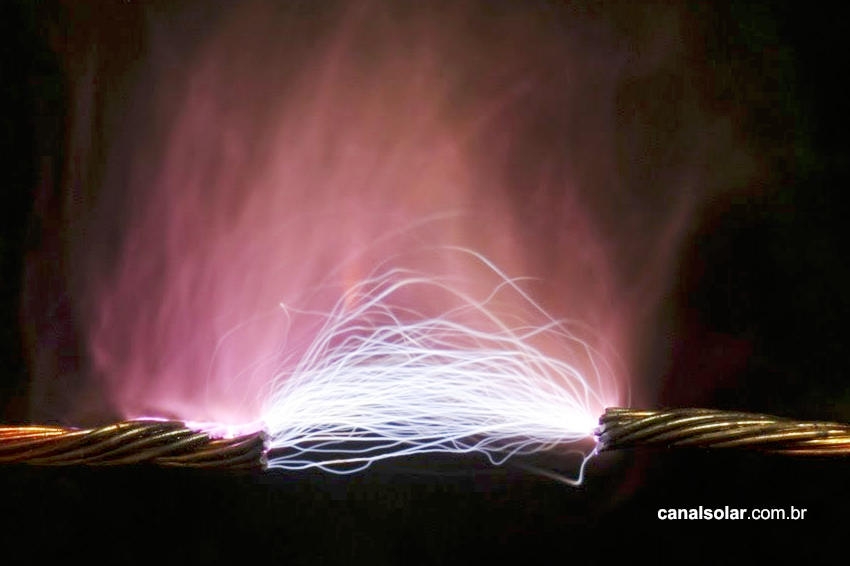
The electric arc
The air around electrical installations can be considered a good insulator, such that for a voltage difference between two exposed conductors 10 cm apart to form an arc and conduct current, a voltage of around 300 kV is necessary. When this insulation limit, also called dielectric strength, is exceeded, an electric arc is formed. The electric arc is the path that a current takes when the dielectric strength of air is overcome. The flow of current in an arc contains enough energy to transform the air around it into plasma, causing great heating of the medium (in welding machines that use an electric arc, this temperature varies between 3000 °C and 20,000 °C) and emission of visible light. Arcs can also be formed when a conductor is cut or severed while carrying current. The current flowing through the arc may even have values close to the current that flowed before the conductor was cut, making the action of protection devices difficult.
Electric arc in photovoltaic systems
Arcs in photovoltaic systems have an aggravating factor: the current and voltage involved are continuous. Arcs in alternating current systems are easier to extinguish, since by the very nature of the system the current and voltage vary. and reach the point of zero voltage several times per second.
The video below demonstrates the difference in intensity and arc formation in systems with the same voltage, but varying between direct current and alternating current.
Video 1: Arc formed by four 250 Wp panels connected in series. The open circuit voltage of the array is 149.6 V
Arcs in photovoltaic systems arise mainly in two ways: poorly made connections or between cables with compromised insulation. This article focuses on analyzing poor connections.
The connection points most subject to arcing are connections between modules or between modules and inverters or string boxes. The connectors adopted worldwide in photovoltaic systems follow the MC4 standard.
The MC4 type connector is built to minimize the risk of bad contacts – it has a robust connection mechanism, when disconnected it has no exposed metal parts and has good electrical insulation.
However, it should be noted that opening a connector while the system carries current is dangerous and is prohibited by connector manufacturers and by the standards governing photovoltaic systems, as there is a risk of electric arc formation upon disconnection from the system. in operation.

String boxes concentrate most of the connections and do not have as robust a connection mechanism as MC4 type connectors.

The connection between conductors and the terminals of internal devices (fuse holder, circuit breaker, disconnector switch and DPS) must follow the specifications of the respective manufacturers.
It should also be noted that it is prohibited to attach cables to devices without any type of suitable plug, terminal or termination.
The direct connection of cables to the devices does not support mechanical stresses nor does it guarantee a good electrical connection, which would already generate a possible heating problem in addition to the risk of the cable coming loose and causing an electric arc inside the string box.

It should also be noted that most devices do not support a derivation or parallelism directly at their terminals. If there is a need to do so, the parallelism or derivation must be done through specific terminals for this purpose.

To ensure that the cables are properly secured, the torque limits of the connector screws must be respected. A screw with a torque below that recommended poses a risk of cable loosening and consequently an electric arc.
A screw with excessive torque can crush the cable, damage the terminals or damage the structure of the device itself.
The electrical terminals of any device (circuit breaker, fuse holder, terminals, etc.) have a torque specification. This specification can be found in the device datasheet or, in some cases, on the device itself.
Few installers observe this specification and the need to use a torque wrench when making electrical connections is almost always neglected. Given the risk of fire that exists in photovoltaic systems, the practice of making good connections and observing the manufacturers' specifications is of great importance.

Table 1: Technical data of the fuse holder in Figure 5, showing the lower and upper torque limits of the terminals 

Care to ensure good electrical connections
Observance of the correct screw tightening torque, as well as the use of suitable terminals to fasten and parallel cables, minimizes the risk of loose connections, bad contacts and electrical arcs that can cause fires in the string box or inverter. .
As already mentioned, the arc formed by photovoltaic systems is direct current, difficult to extinguish and with a high probability of damage.
Installers of photovoltaic systems must always have a torque wrench at their disposal, as well as other tools appropriate for the devices they work with.
Costs for terminals, connectors, tools and cable termination have a low impact on the total cost of the work, while electrical connections are the biggest point of failure in the systems.
You shouldn't save money or “invent crazy solutions” in connections. The physical safety of people and the material security of the system must always be guaranteed first.
In summary, these are some precautions that must be observed in the electrical connections of photovoltaic systems:
- Do not solder connectors of any type (MC4 or others). As a rule, soldered electrical connections are not permitted in electrical circuits. Appropriate connectors must be used for each type of connection;
- Do not splice cables without connectors, with insulating tape or in any other way. In addition to not providing good electrical contact, connections made with insulating tape do not offer the electrical insulation and durability expected in photovoltaic systems;
- Do not connect cables to devices (circuit breakers, fuse holders, terminals, etc.) without using suitable terminals. Terminal inputs must always use eyelet or eyelet type terminals, as applicable. When it is necessary to parallelize cables, double terminals must always be used. In Figure 4, for example, we see a case in which double eyelet terminals should be used;
- Use MC4 connectors of good quality and good origin. Connectors represent a small fraction of the cost of a photovoltaic system, as we have already mentioned. Nothing justifies the use of generic connectors of dubious quality;
- Correctly tighten the electrical connection screws. Correct tightening of a screw must be carried out using a torque wrench and in compliance with the specifications of the appropriate torque value for each type of device, according to the manufacturers' guidelines. The torque wrench function can already be found built into some general purpose tools. Simply replace the original tool (screwdriver, for example) with a tool with adjustable torque, as seen in the figure below. When adjusting the desired torque value, the tool signals (at the end of the tightening procedure) when the specified torque has been reached. This way, the screws are tightened reliably, without less or more torque than necessary.


One Response
Good morning!
Great well-informed presentation.
Helped me a lot.
Thanks