
According to standard NBR 14039 – Medium Voltage Electrical Installations, a medium voltage (MV) cabin must have the following protective equipment, depending on the installed capacity:
a) Installed capacity less than or equal to 300 kVA
- Circuit breaker activated by relays with phase and neutral timed and instantaneous overcurrent protection functions (50/51 and 50N/51N), or;
- Disconnector switch and fuse, as long as it has a general low voltage circuit breaker.
b) Installed capacity greater than 300 kVA
In this configuration, protection is required by means of a circuit breaker activated by secondary relays with phase and neutral functions 50 and 51. Using a medium voltage circuit breaker implies the need for an appropriate location to house it, in addition to peripheral components such as relays, current and potential transformers.
With the advent of ANEEL resolution 482/2012, which deals with agents operating in energy compensation mode, a new classification of consumers in micro and mini generation emerged. This classification is well defined as:
- Microgeneration: installed generation capacity of up to 75 kW;
- Minigeneration: installed capacity above 75 kW and up to 5 MW.
And within this context, energy distributors in Brazil allow several configuration concepts for connecting a customer to the medium voltage system, called A4. Going through the different concessionaire standards, it is observed that there is no consensus on the use of a common configuration, even though the characteristics of each region of the country are preserved. But we can highlight at least two aspects:
- Allow the use of medium voltage fuse switches and;
- Require the use of a medium voltage circuit breaker.
Another important issue concerns the billing measurement system for A4 customers. According to NBR 14039, measurement can be at low voltage if the installed capacity is up to 300 kVA. Above this value, the measurement must be at medium voltage.
Thus, the location of the measurement sector is another important factor in the configuration of a primary cabin. We will deal here with the protection aspects using the typical concepts of 2 concessionaires for minigeneration – Celesc and CPFL – in accordance with their technical standards:
- CELESC: I-432.0004 – Requirements for connecting micro or mini power generators to the Celesc Distribuição electrical system
- CPFL: GED 15303 – Connection of distributed micro and mini generation under electrical energy compensation system
Reference Diagrams
To deal with the 2 typical configurations, the schemes adopted by CELESC and CPFL are presented, shown in Figures 1 and 2.
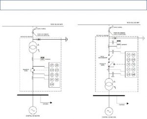
Figure 1: Primary cabin configuration according to Celesc
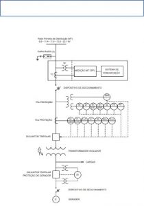
Figure 2: Primary cabin configuration according to CPFL
Comparisons
Observing the diagrams, it is clear that companies already have differences in relation to the way they are classified. While Celesc treats it in terms of apparent power, CPFL treats it as active power. The Celesc standard does not make any mention in the text regarding the use of a fuse switch on the medium voltage side, but the adopted configuration indicates the use of a fuse switch (Figure 1).
On the other hand, CPFL does not allow the use of a fuse between the connection point and the generation, based on technical standard GED 33 (Connection of Self-Producers in Parallel with the CPFL Distribution System), item 6.1: “…It should be noted that the use of fuses or single-pole disconnectors between the input switch and the generator or generators is not permitted.” This requirement is ratified in the configuration shown in Figure 2.
The same restriction is also required by Prodist Module 3, section 3.3: “5.4.8 Single-pole fuses or disconnectors must not be used between the input circuit breaker and the generators.”
However, this item is not highlighted in section 3.7, which deals with micro and minigeneration procedures. Specifically dealing with protection functions, particularly on photovoltaic generation, the diagrams shown in Figures 1 and 2 indicate that they must act on the respective circuit breakers, although some protections can be performed by inverters.
Table 1 presents the protections required by Module 3 and that can be enabled in the relay and/or inverters.
Table: Protection functions of relays or inverters
|
Protection |
Function |
Description |
Qualification |
|
|
Relay |
Inverter |
|||
|
Conventional |
50/51 |
Phase overcurrent |
X |
|
|
50N/51N |
Neutral overcurrent |
X |
|
|
|
Complementary |
59N or |
Neutral overvoltage |
X |
|
|
67N |
Neutral directional overcurrent |
X |
|
|
|
32 |
Power directional |
X |
X |
|
|
25 |
Timing |
|
X |
|
|
27 |
Undervoltage |
X |
X |
|
|
59 |
Neutral overvoltage |
X |
X |
|
|
46 |
Current imbalance |
X |
|
|
|
47 |
Voltage unbalance |
X |
|
|
|
51V |
Overcurrent with voltage restriction |
X |
|
|
|
67 |
Phase directional overcurrent |
X |
|
|
|
78 |
Phase angle measurement |
X |
|
|
|
81 O/U |
Over and under frequency |
X |
X |
|
|
y/n |
Anti-islanding |
|
X |
|
When protections are performed by relays, there is a need to install current transformers (CTs) and potential transformers (PTs) appropriately installed to detect signals on the medium voltage side. For example, the 59N function requires the use of three VTs on the medium voltage side, as well as the overcurrent functions require 3 CTs.
These needs imply the existence of a suitable environment, that is, a medium voltage cabin. In general, Table 2 presents the main characteristics between the configurations of the two concessionaires.
Table 2: Characteristics of primary cabin configurations for two dealerships
|
Device |
Celesc |
CPFL |
|
|
P ≤ 300 kVA |
P > 300 kVA |
P > 75 kW |
|
|
MT fuse switch |
Yes |
Yes |
No |
|
Circuit breaker at MT |
No |
Yes |
Yes |
|
Protection actions |
BT |
MT |
MT |
It appears that CPFL, for any minigeneration, requires the use of an MV circuit breaker.
Comments
This article dealt with configurations adopted by two dealerships and the two lines of configurations still suffer from variations in some dealerships. It can be said that the configuration adopted by CPFL is similar to that of Elektro and Roraima Energia. The configuration adopted by Celesc, with some variations, is followed by Copel and Cemig.
At Copel and Cemig there are variations regarding the use of inverters and depending on the power and type of substations. In any case, these variants affect the cabin specification, reflecting the cost of implementing the plant. When it comes to photovoltaic generation, it would be appropriate for there to be the same procedure between concessionaires and some optimizations could be evaluated:
- Use of fuse switches in the MV, with simultaneous opening feature between phases;
- In situations where there is no space to build or install a primary cabin, evaluate the possibility of using pole reclosers and time measurement;
- Tele-protection between the distributor's protections and the plant's protections (relay and/or inverters).
Bibliography
- NBR 14039 – Medium voltage electrical installations
- Prodist Module 3
- Resolution 482/2012 – ANEEL
- GED 33 – Connection of Self-Producers in Parallel with the CPFL Distribution System
- GED 15303 – Connection of Distributed Micro and Minigeneration under Electricity Compensation System – CPFL
- I-432.0004 – Requirements for the Connection of Micro or Mini Power Generators to the Electrical System of Celesc Distribuição – CELESC
- DT – DTE 01/NT 001 Distributed Micro and Minigeneration Access in the Roraima Energia Distribution Network
- NTC 905200 – Distributed Micro and Minigeneration Access to the Copel System (with energy compensation)
- ND 5.31 – Requirements for Connection of Electricity Producers to the Cemig D Distribution System – Medium Voltage


4 Responses
Great article, I'm studying the Selesc standard: I-432.0004 and these clarifications helped me a lot.
We appreciate the recognition, Eduardo!
Congratulations and thanks for the article!
Hi, good evening, I'm already looking forward to training.