
The design of the photovoltaic system must consider several technical aspects such as the gauge and length of the cable, the voltage drop in the circuit and the difficulties that may be encountered in carrying out the physical work.
In this article, we will address the voltage drop in the direct current circuit by exploring a real case. During the project, there was a doubt about the best way to arrange the inverters. Should they be positioned close to the photovoltaic modules or next to the property's power supply point?
A loss analysis indicates that the best solution would be to position the inverters close to the property's entry point. This minimizes generation losses, as it shortens the alternating current cabling and causes greater distances to be covered by the direct current circuit, in which the voltage is higher and the current is reduced.
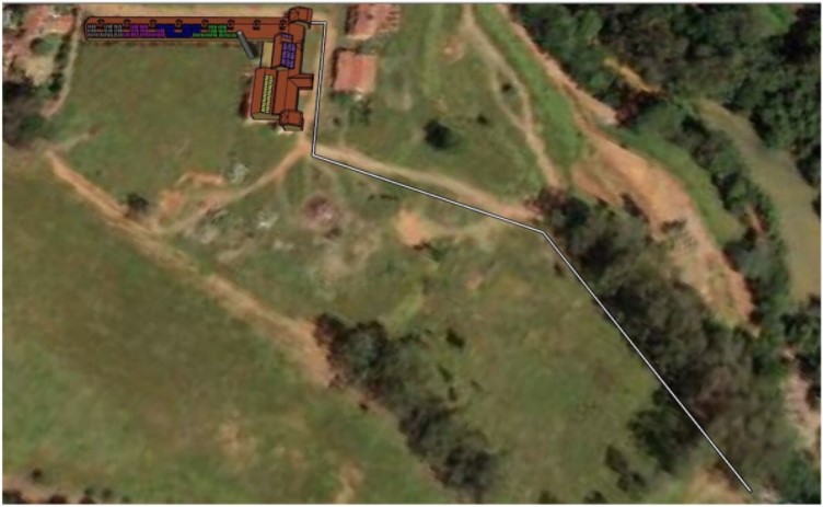
The photovoltaic system was installed on a rural property where there is a considerable distance from the construction area to the power supply point. It was preferred not to connect the photovoltaic system to the building's internal circuit, as it was an old installation.
The connection of photovoltaic systems to existing distribution boards, especially in old or poorly sized installations, often causes problems with voltage variations and unwanted shutdown of the inverters.
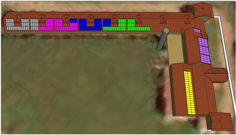
In Figure 2 we observe the positioning of the strings over the roof. An inverter with 12 MPPT inputs was used. The longest circuit, called MPPT1, has a total length (considering the positive and negative cables) of 920 meters. It is on this circuit that we will perform our voltage drop analysis. The distances from each string to the inverter are shown in Table 1, below.
Table 1 – Distances from strings to the inverter: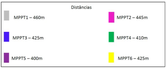
The voltage drop problem
A known problem in the area of electrical installation design is the voltage drop in cables. Two criteria are used when sizing a cable or electrical conductor: current carrying capacity and voltage drop.
In long circuits, even if the conductor gauge meets the current conduction criterion, the voltage drop criterion will not always be satisfied. In this case, the solution to be adopted is to use a larger gauge cable, which increases the cost and complexity of the installation.
A photovoltaic project is, above all, an electrical installation project. Low voltage installations in general are governed by the NBR 5410 standard and photovoltaic installations are governed by the NBR 16690 standard.
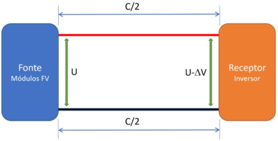
The two complement each other, and the NBR 16690 standard concerns more specifically direct current circuits, whose specificities were not addressed in the first standard mentioned. The percentage voltage drop in a direct current circuit is calculated as:
Drop (%) = Delta_V / U
Delta_V = R x I
R = r * C
Delta_V is the voltage drop in the circuit (V), U is the source voltage (V), R is the conductor resistance (ohms), I is the intensity of the electric current (A), C is the total length of the circuit (m) er is the resistance per unit length (ohms/m) of the cable found in the manufacturer's catalogue.
The NBR 16690 standard says the following:
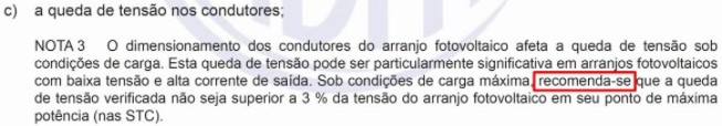
The standard recommends, but does not require, that the voltage drop in the DC circuit is not greater than 3%. Whenever possible, the guidance in the standard should be followed. If the guidance is not followed, the designer must rely on his experience and other technical factors to make the best decision.
What would be the problem with a high voltage drop in the DC circuit? The answer is just one: loss of generation. Voltage drops cause energy losses that accompany the photovoltaic system throughout its useful life. However, losses will always exist and can only be minimized by expanding the cable gauges, which consequently costs and complicates installations.
Project premises
Two gauge options were possible: 6 mm2 or 10mm2. With 6 mm gauge2 connections would be made easier, as the inputs of the inverter used in the project have receptacles for connectors up to 6 mm2, as shown in Figure 4.
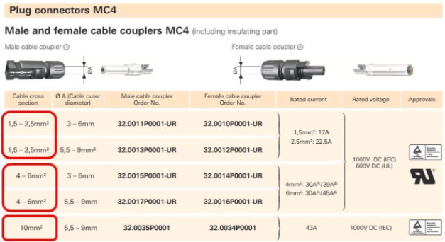
In Figure 4 we see that the inverter has 6 MPPTs and 12 inputs for connecting circuits, two inputs per MPPT. In this project each string was connected to one of the 12 inputs. You MC4 connectors are standardized in two versions: 1.5 and 2.5 mm gauges2, 4 and 6 mm2 and 10 mm2, as can be seen in Table 2 below.
Using 10 mm cables2 would make it impossible to use MC4 connectors for direct connection of strings to the inverter, making it necessary to create string boxes external. In addition to the additional cost of adding string boxes, the adoption of 10 mm cable2 it would make it difficult to lay the cables in the duct destined for the direct current circuit.
The challenge of this case study, therefore, was to prove the feasibility of adopting the 6 mm cable2 in this project, which has long circuits – one of the strings requires almost 1 kilometer of cables.

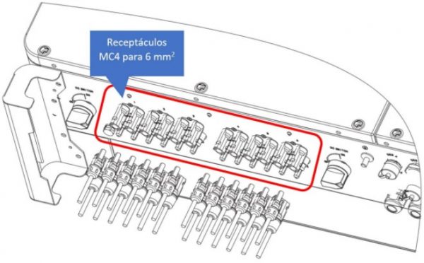
Table 2 – Standard gauges for MC4 connectors:
Voltage drop calculation
Below we find the table with the characteristics of the cables used in the project (Cortox Solar/Cordeiro Cabos Elétricos).
Table 3: Technical characteristics of Cortox Solar/Cordeiro Electrical Cables: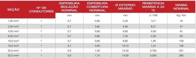
In accordance with guidance from NBR 16690, voltage drop is calculated with reference to the voltage at the point of maximum power in STC (standard test conditions: 1000 W/m2 and 25 OW). The information we need to extract from the table is the resistance of the conductor. We find in the table: r = 3.39 ohms/km for the 6 mm cable2 er = 1.95 ohms/km for 10 mm cable2.
In this project, with 20 modules in series, with a maximum individual power voltage of 40.3 V in STC, the total voltage is 806 V. The allowable voltage drop would therefore be: 3% x 806 = 24.18 V. At maximum load condition, the current of each string is I = 11 A.
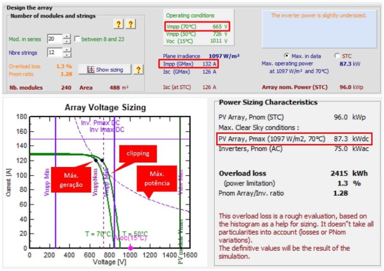
This number was found by dividing the total current (132 A, as shown in Figure 5) by the number of strings, which is 12. The maximum load condition was obtained from the system sizing in PVSyst.
Considering a typical operating temperature of 70 OC, the system reaches a maximum power of 87.3 kW (which also corresponds to the maximum input power of the inverter). This is an example of good compatibility between the characteristics of strings and the inverter. The occurrence of clipping will be very small in this project.
From the point of view of calculating the voltage drop, the consideration made is correct, as it represents the maximum generation power that can be achieved with this system. At lower temperatures, the system's IV curve (green trace) will be shifted to the right, causing the power to be limited to the maximum value that the inverter can support (represented by the dashed line). If the temperature is greater than 70 OC, the maximum load condition will have power lower than the value considered.
With all the data in hand we can proceed to calculate the voltage drop for the 6 mm cable2:
r = 3.39 ohms/km ; C = 0.92km; I = 11A; U = 806V
R = r * C = 3.1188 ohms
Delta_V = R * I = 34.3 V
Drop (%) = 34.3 / 806 = 4.25%
The calculation reveals that, in accordance with regulatory guidance, the limit of 3% of the maximum power voltage at STC is violated. However, some considerations about this are necessary.
Firstly, the voltage drop limit in NBR 16690 is a recommendation. Voltage drop greater than 3% is not a prohibition, as it does not pose any safety or risk of any kind to the system. It should only be borne in mind that the presence of excessively high voltage drops would result in generation losses.
In this case, however, the calculated voltage drop is very close to the recommended limit and occurs in only one of the 12 strings. In cases like this, the designer must evaluate the convenience of respecting the 3% limit or choosing a higher gauge cable.
In this project, the option of increasing the gauge to 10 mm2 This would cause difficulties in laying the cables and reduce the safety of the system by increasing the complexity and number of components and electrical connections. There would also be an increase in cost, which would not justify the benefit of reducing generation loss – a negligible benefit, in this case, as verified in a simulation carried out at PVSyst.
Conclusion
The maximum recommended voltage drop in photovoltaic systems is 3% in direct current circuits. This drop is calculated based on the maximum power voltage of the string of photovoltaic modules in 25 OC and 1000 W/m2 (STC condition).
Voltage drops greater than 3% are permissible, as long as they do not significantly impact the performance of the photovoltaic system. This impact must be measured and evaluated through simulations in PVSyst. Aspects such as cost, complexity and safety must be analyzed together with the other design criteria for an installation.
In the case analyzed, it was found that the best option would be to use a smaller gauge cable instead of the superior cable. In the analyzed circuit, referring to one of the 12 strings of the system, the benefit of the larger gauge would be negligible, not justifying the inconvenience of adopting it.
To understand more about cable sizing criteria in photovoltaic systems and other design considerations, be sure to check out the solar energy courses from Canal Solar!
Collaborating on this study were: Elvis Almeida and Guilherme Sanches – from MySol Energia Solar – and Micaella Aynoã.


3 Responses
Excellent case study, congratulations on the article! Cleared my doubts!
It is the module current
Cool, Marcelo,
I just didn't understand the 11 A current (i) very well. How did you find it?