In mid-2021 the SolarEdge Designer gained the DXF (Drawing Exchange Format) file import tool.
This file format is used in exchanging CAD (Computer Aided Design) models such as AutoCAD and similar.
The possibility of bringing drawings into SolarEdge Designer makes model development more accurate and facilitates the positioning of photovoltaic modules in the available area.
Previously, when importing the DXF file was not possible, designers had to be guided solely by the dimensions of satellite images.
Despite the relatively good accuracy of these images, the possibility of working with measurements that can be pre-defined by the user is always welcome in any drawing or design tool.
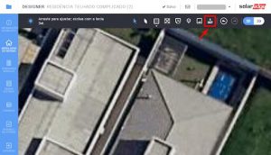
In the “System Modeling” tab, choose the DXF icon in the top left bar, as shown in the figure below.
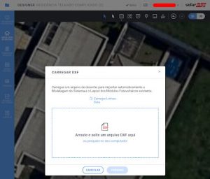
SolarEdge Designer then prompts you to drag or select the DXF file to import from your computer:
The next step is to associate the roof design with a layer available in the DXF file. Drawings made in AutoCAD normally have the default layer “0”, but any other layer can be used. It is recommended, when preparing the DXF file, to exclude all objects that are not part of the drawing and keep them on the same layer.

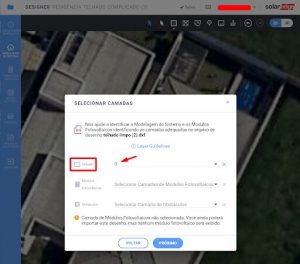
Layers can also be selected for photovoltaic modules and obstacles, if these elements are present in the drawing. In this example we will only import the roof design, keeping the other layers inactive.
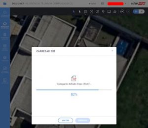
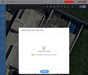
After selecting the layers, the import process will begin. Attention: this process may fail if your DXF file contains many unused objects, such as other layers, exploded blocks, and objects that may be located outside the drawing viewing area.
It is recommended to run the AutoCAD PURGE command (or another similar command, if you use another tool) to clean up the drawing before creating the DXF file.
If you don't have AutoCAD or other CAD software, a tip is to use the “DWG to DXF Converter” tool available online on the website www.cloudconvert.com
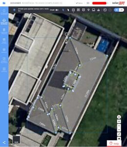
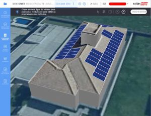
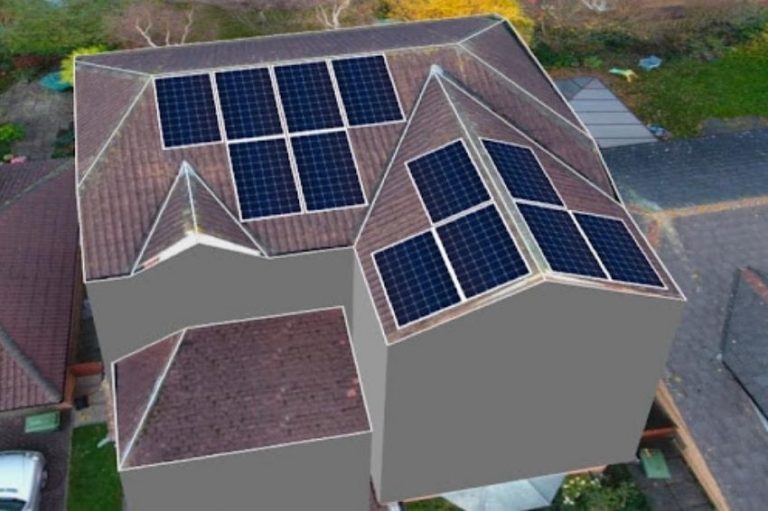
Once the export is complete: voilà. The only work the designer needs to do is position the imported design on the satellite image and then finalize the modeling, defining the Z-axis dimensions of the roof and existing obstacles.