The PID (Potential Induced Degradation – potential-induced degradation) is an unwanted effect of photovoltaic module degradation that can cause significant power losses over time.
An array of photovoltaic modules connected in series has a total voltage equal to the sum of the voltages of the individual modules.
As the cells inside the module are connected in series, we can view this arrangement as a series circuit containing all the cells.
The high voltage to which each cell is subjected can give rise to unwanted leakage currents between the cells and other parts of the modules.
The metal housing of the modules is always grounded, therefore in inverter topologies that do not allow the positive or negative pole of the photovoltaic array to be grounded, there is a potential difference between the cells and the housings or between the cells and the glass.
For example, a photovoltaic module has around 35 V voltage during operation. If this module is connected in series with 20 other modules, there is a string voltage of 700 V.
Ideally, the voltages of the positive and negative poles should be symmetrical in relation to the ground voltage.
If this is true, the cells closest to the negative pole will be at a potential difference of -350 V in relation to the metal housing of the module. The figure below illustrates the voltage distribution of a photovoltaic array.

This negative potential difference can induce a leakage current between the cells and the other elements of the module, causing ion mobility that is detrimental to energy generation.
This mobility reduces the cell's generation efficiency as it disturbs the charge balance of the semiconductor necessary for current generation. Mobility can also cause internal corrosion of module components.

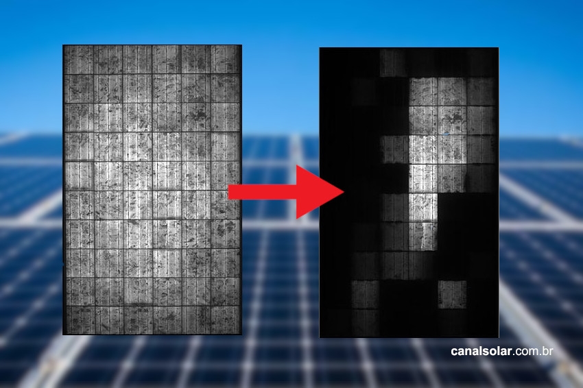
The PID effect is most prominent when there is negative voltage between the cell and ground. The distribution of the most affected cells in an array is shown below.

External environmental factors also have an influence on the intensity of the PID effect on the module. High humidity decreases the resistance between the module's metallic casing and ground, and high ambient temperature increases ion mobility, thus increasing leakage currents between the affected cells and module components.
An important source of unwanted ions comes from the construction of the modules themselves. Low quality glass can release sodium ions during the emergence of this leakage current and low quality encapsulants allow greater moisture permeability in the module, worsening the effects of PID.

The relationship between inverters and the PID
There are two inverter topologies available for the solar market: with or without an internal transformer.

Inverters with an internal transformer have a transformer responsible for transmitting energy from one inverter circuit to another through the magnetic medium, that is, the energy input and output are electrically separated by the transformer.
These inverters can also be called galvanically isolated. In this type of inverter, it is possible to connect the ground to the negative pole of the arrangement, thus reducing the negative voltage that influences the appearance of the PID.
Transformerless type inverters are the most common on the market, as they have some advantages such as lower cost, size and weight and greater efficiency.
However, in this type of inverter it is not possible to connect the ground to the poles of the photovoltaic array. If this occurs, the inverter will shut down to prevent damage.
In this type of topology, the positive and negative voltages of the arrangement are typically symmetrical to the ground voltage. Therefore, this type of inverter favors the appearance of negative voltage that increases the PID effect.
How to mitigate the PID effect
There are some actions that can be taken to mitigate the PID effect. The main one is to select quality modules, in which manufacturers have used materials that reduce the PID effect to close to zero, increasing the electrical resistance between the cell and the metal housing, reducing the entry of moisture and reducing the availability of ions. provided by the module materials with the use of good quality glass.
If it is an option compatible with the project, inverters with an internal transformer can also be used, since this topology allows the negative conductor of the array to be grounded, which helps to reduce the PID effect.
There are also some technologies that can be integrated into inverters or applied to other equipment that reduce the PID effect.
During the night, the inverter or equipment supplies a voltage opposite to the arrangement's operating voltage.
As the PID arises from the polarization between the cells and the panel, applying a counter voltage reverses the polarization that occurred during the day.
Some of the negative effects of PID can be reversed by applying this reverse voltage.

In general, already installed photovoltaic projects can operate with string voltages of 1000 V and, with the advancement of module and inverter technologies, systems that operate at 1500 V are already becoming popular.
The industry's move to migrate to higher operating voltage systems will make anti-PID measures increasingly necessary.