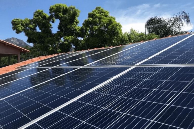
Ceramic roofs are the absolute majority in residential construction, therefore, the professional career of a photovoltaic system installer will probably involve ceramic roofs.
The apparent simplicity of this type of roof can hide some mistakes or poor design decisions that can lead to roof damage or damage to photovoltaic systems.
It is worth mentioning that the correct choice of structure and module allocation must also be seen from the perspective of the module installation manual, which is often ignored in this type of project.
Module Manual
All module manufacturers have an installation manual for their products. And, as a rule, product warranties are linked to the observation of the items in this manual.
From an installation care point of view, we can list the main points covered by these manuals:

- Prohibition of modifications (holes) in aluminum frames;
- Minimum space between the module and the roof;
- Minimum distance between modules;
- Minimum recommended slope for water and dirt drainage;
- Possible support points for the modules in the structure;
- Acceptable materials for fixing and grounding screws.
In addition to cleaning recommendations, storage and transportation of products. Although not always available on the photovoltaic kit's documentation page on the distributor's website, it is essential that it is requested and read to avoid assembly errors, as we will show in the next section.
Main assembly errors on ceramic roofs
Roof assembly errors are not limited to failure to follow the module, microinverter and optimizer installation manuals.
We may have some related errors, including failure to observe the photovoltaic system standard NBR 16690. The main installation errors on ceramic roofs are listed below:
- Lack of general analysis of the roof structure: Roofs are usually designed to support their weight with little room for extra weight. Depending on the size of the photovoltaic system and the strength of the winds, we can have much higher mechanical loads than imagined when designing the roof;
- Analysis of rafters and slats: The fixing hooks for metal structures are attached to the roof rafters, so it is important to check the condition of the wood. The slats that support the tiles, in principle, should not receive the weight of the modules, however, if they are in poor condition they will weaken the roof and the rest of the installation;
- Old or fragile tiles: Very old tiles tend to be more brittle, making the installer's job difficult. When faced with this type of roof, special care must be taken not to break the tiles;
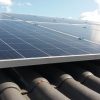
- Re-roofing after installing the support: After fixing the metal hook to the rafter, it is necessary to relocate the tile above it. The hook fixing can be misaligned in relation to the ridge of the tile, which in turn can cause a greater gap between the tiles and eventually the entry of rainwater;
- Some roofs may have a layer of waterproof blanket underneath the tiles. Installation must be careful not to puncture or damage the waterproof layer.
Regarding modules, microinverters and optimizers:
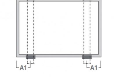
- The module manual specifies on which sides and the greatest distance between the metal supports on which the module can be installed. Installing the module supported only on the edges of the longer side (see figure) causes greater deflection of the module and can cause microcracks in extreme wind events.
- In general, manufacturers do not allow extra holes to be drilled in modules for fixing or grounding. It is necessary to check in advance, in the design phase, whether the installation of the modules will be possible without this improvisation;
- The aluminum of the module frame can expand with temperature. Manufacturers recommend at least 1 cm between modules to alleviate the problem;
- The aluminum of the module frame and the aluminum of the fixing structure are not good conductors. Simply touching one another does not guarantee good equipotentialization. In addition to the fact specified in the installation manual, the NBR 16690 standard states that we must make the modules equipotential. Equipotentials where there is no other element (cable fixed with a screw, grounding clamp) do not comply with the standard and do not represent good equipotentialization;
- The module installation manual specifies a minimum height between the roof and the module. This concern is mainly related to the thermal performance of the modules, in addition to avoiding cable crushing or bending that could damage them.
- The same observation of minimum distance and equipotentialization are valid for microinverters and optimizers: both can suffer from high temperatures if the minimum distance is not observed. The simple fact of touching this equipment to the aluminum structure of the module or support is not enough to guarantee good equipotentialization;
- Metal structure manufacturers also provide installation manuals! It is essential to read this material.


5 Responses
Learning a lot from the site's content. Congratulations and thank you!
Thank you for the information, I would like to add about the colonial tiles manufactured in the south of the country, which have a fine finish and light colors, the only way to avoid leaks is with a cut in the tile in the support area and with an external finish in PU40 This way we avoid punctures and have a perfect finish and zero risk of drips.
Abs,
MERAK Sustainable Engineering.
I would also like more information about Solar Energy, as I intend to market myself as a Management and Sales Engineer for a Gde Solar firm for the Ribeirão Preto region as I am a Mechanical and Production Engineer with around ~ 50 years of experience in Project Management in Engineering area.
Good afternoon, thank you very much for the information, I am interested in taking Solar Energy installation and sales courses and gaining more knowledge about solar energy. I am a construction contractor and I intend to be part of the future of solar energy, which is expanding.
Very good article