
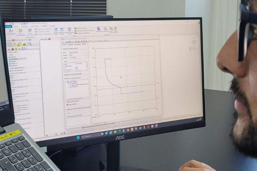
Managing protection device settings is one of the main features managed by the Ampère Professional software.
Obtaining the actual calibration values provided for in the protection within the adjustment ranges is one of the functions managed by the software, which provides specific values of the minimum and maximum adjustment limits of the protections according to the manufacturers' catalogues.
This information helps the designer to consult the data and consequently provides the installer with the correct value to be defined in the protections, avoiding interpretation errors.
It is also possible to apply tolerances when adjusting protections with the software. Manufacturers normally provide, in percentage terms, the tolerance associated with the protection intervention, that is, their degree of precision in the intervention on the current passing through the protection.
Each trigger function (long delay, instantaneous, etc.) can have its own tolerance, differentiated from the other functions.
Therefore, the activity of carrying out the selectivity check is simpler and has made the designer's task much more effective, freeing him from direct contact with the manufacturer and, in some cases, avoiding delegating the correct adjustment of the protection to him.
Calibration and adjustment of protections
Curves Panel
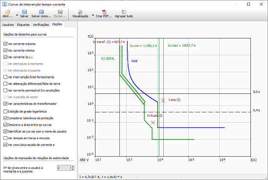
The Ampère software has two windows to represent the protection intervention curves: the Time-Current Intervention Curves window and the Curves advanced functions panel.
Specifically for the activity of adjusting protections for selectivity purposes, it is recommended to use the Curves panel, which allows you to quickly choose the users/protections to be controlled by acting directly on the Mesh.
The panel features a command bar for choosing a display mode for the curves associated with selected users.
- Selectivity with selected users: up to 8 users selected in the Mesh are represented on the panel;
- Selectivity with favorite and selected users: the user set is created from the users marked as “Favorites” followed by the selected additional users, up to a maximum of 8 users;
- 1, 2, 3 selectivity levels: the three commands add 1 to 3 “useful” user levels upstream of the selected one;
- User evidence on selectivity: At the right end of the command bar, there is the command with which users will be outlined with the color equal to the selectivity level, especially convenient for systems with many users and different frame “levels”. It is advisable to activate this last option to make it easier to read the situation and make adjustments.
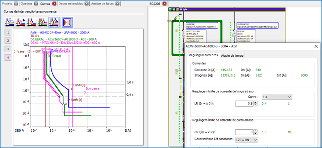
Calibrations
To access the Calibrations window, simply select the numbered command relative to the selected user. The button numbers, also colored, indicate each user's mesh level in relation to the selected set.

Furthermore, by clicking the mouse on a curve, with the cursor in the shape of a cross, the software opens the Calibrations window. When editing settings, Ampère updates the curves automatically, allowing for quick and easy adjustment.
Editing settings follows the rules defined in the Protection Settings tab, and the window adjusts and corrects values that deviate from expectations. This is where the first of the new features described in the introduction comes into play: by passing the cursor over the adjustment range fields, the software proposes the Step or Steps of protection.
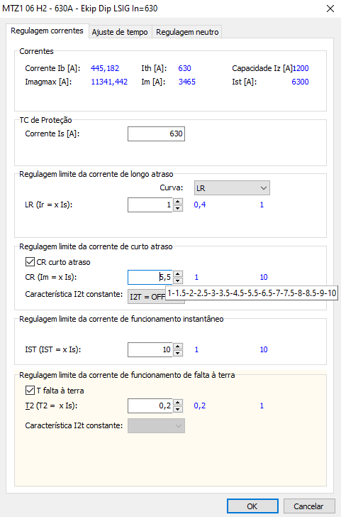
Type of calibrations: free, discrete and steps
The free, discrete and step options are the three types of calibration managed by the software for protections that have adjustment ranges and, therefore, with accepted values between Minimum and Maximum.
- Free: Unrestricted adjustment values are permitted. The software does not display comments in the Calibration window above the adjustment ranges, but accuracy of up to 0.0001 Amps or seconds is supported.
- Discreet: the adjustment has a Step, which is an incremental value between one adjustment and the next.
- Steps: tuning must be chosen within a finite set of tuning range values.
Using the “increase/decrease” arrow commands next to the edit boxes, the software provides the correct values, respecting the values in the file and the manufacturer's rules. Any values entered directly into the edit box will be checked in the window output to be consistent with the protection rule.
Fit Tolerance
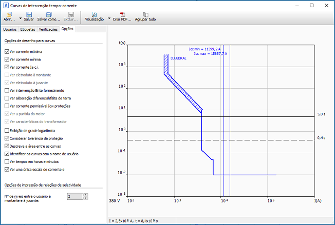
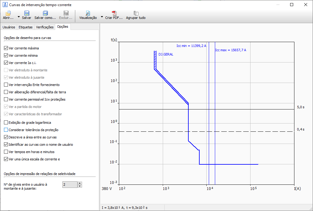
The protections used in the project may have percentage error values related to current, time or both, within which the trip unit is guaranteed. The software represents the time/current intervention of the relays through two curves, lower and upper, separated by twice the tolerance, multiplied by the current and the average time.
The two curves represent the maximum and minimum limits; the area inside it represents the possible field of protection intervention. This area can be hatched, increasing the legibility of the graph and facilitating calibration operations to obtain ideal selectivity for the electrical network under analysis.
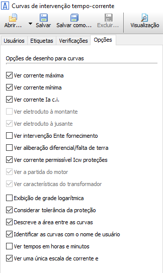
To visualize the effect of tolerances and the hatching of areas on the graphs, the Consider protection tolerances, Describe the area between curves options must be activated in the Options tab of the Time/Current Intervention Curves window. In conclusion, precision regarding Long delay protections and the operating range represented in the tripping curves is appropriate.
For these protections, the variable Relation of intervention current over the threshold dIr (for Selectivity Check) has always been available, with which manufacturers define the maximum safe intervention value of the Long delay trip.
The software represents the Long delay with two curves: one curve at the calibration value and another at the calibration value multiplied by the Ratio dIr. If a long delay trigger tolerance is also associated, these values will be expanded further by the tolerance.
The opinions and information expressed are the sole responsibility of the author and do not necessarily represent the official position of Canal Solar.