

Reverse current is a phenomenon that can occur in photovoltaic installations that employ centralized inverters, to which many strings are generally connected in parallel.
This situation is frequently found in larger minigeneration systems and centralized plants, but can also occur in smaller inverters with strings connected to the same input.
In principle, reverse current will only occur when strings connected in parallel have different open circuit voltages.
In normal situations this problem should not occur, since parallel strings must always have the same number of modules (SMA, 2009) (VINTURINI, 2019).
It is known that module shading has no significant effect on open circuit voltage. In the faultless operation of a correctly dimensioned photovoltaic plant, no excessive reverse current can occur (SMA, 2009).
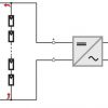
The reverse current will occur in rare cases of total shading of a string (SPERTINO; AKILIMALI, 2009) or, more commonly, in case of faults that cause short circuits in the modules, reducing the total open circuit voltage of the strings, as illustrated Figure 1.
Reverse current protection
Reverse current must be prevented by using fuses in series with the strings. The application of fuses is provided for in the standard for photovoltaic electrical installations NBR 16690. Typically, the application of the standard's guidance determines that arrangements with three or more parallel strings must receive fuses in all strings.
An alternative that was considered in the past was the use of blocking diodes placed in series with the strings. Theoretically diodes would eliminate the use of fuses by preventing or blocking reverse currents in the strings. However, according to IEC TS 62257-7-1: 2010, blocking diodes are a source of failures and energy losses and their use is not recommended.
The use of a series fuse, normally housed in the stringbox, is the solution widely used in photovoltaic installations to avoid reverse current. Even with the presence of fuses, there are reports of current circulation and damage to modules, the probable cause of which is the failure of the fuses to operate.
Reverse current caused by voltage mismatch between modules
In addition to the large number of parallel strings, minigeneration photovoltaic systems and centralized generation plants work with high DC voltages, with long strings, which have a large number of modules connected in series.
High voltage strings are interesting because they simplify installation, reducing the number of circuits and consequently cabling costs.
Increasing the length of the strings – that is, the number of modules connected in series – in a solar plant produces a problem known as mismatch, which can be translated as incompatibility or mismatch between the different modules in the string. We can talk about voltage, current or power mismatch.
There is a natural voltage mismatch due to small variations in the open circuit voltages of the modules that make up the strings. An even greater mismatch between strings can occur in situations of partial shading or non-uniform lighting of the modules, which can occur mainly due to the passage of clouds or dirt.
Voltage mismatch between strings could be pointed out as a cause of reverse current circulation in photovoltaic installations. However, mismatch due to causes that we can call natural (differences in module manufacturing, shade or dirt) would hardly be able to produce reverse current in the modules.
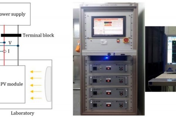
An interesting study conducted by the Korea Renewable Energy Institute (SHIN et al., 2019) shows the effect of voltage mismatch on a photovoltaic module. Although the experiment was performed with just one module, the same observations could be extended to a string with any number of modules.
Figure 2 shows the experiment setup, which consists of applying an adjustable voltage source in parallel with a photovoltaic module. An artificial light source made it possible to study the behavior of the photovoltaic module under different levels of solar irradiance.
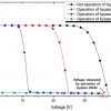
The result of the experiment is shown in Figure 3. The graphs show the reverse current of the photovoltaic module as a function of the voltage applied to it by the external source for different values of solar irradiance.
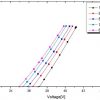
The conclusion drawn from Figure 3 is that a very large voltage mismatch is necessary to cause significant reverse current circulation in a photovoltaic module.
The open circuit voltage at STC of the module used in the experiment is 37.14 V. At 1000 W/m2 the reverse current begins to circulate from this value, as seen in the graph.

The reverse current reaches high intensity, close to the module's short-circuit value, only when the power supply voltage is raised to more than 40 V.
The voltage mismatches found in practice due to variations in solar irradiance or dirt are small, insufficient to cause the circulation of a dangerous reverse current, as shown in Figure 4.
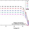
Another hypothesis that can be raised regarding the origination of reverse current is regarding voltage mismatches caused by the operation of the bypass diodes in situations of partial shading of the modules.
A second part of the experiment conducted by (SHIN et al., 2019) shows that even with partial shading, when the activation of the bypass diodes could occur, the variation in the module's open circuit voltage remains small in relation to the nominal value (in STC), as shown in Figure 5.
Reverse current caused by failure of bypass diodes
Research conducted by (SHIN et al., 2019) also investigated the conditions encountered when bypass diodes fail. Defective bypass diodes usually correspond to a permanent short circuit on the cells of the photovoltaic module, which considerably reduces the module's output voltage.
The application of voltage above the reverse breakdown voltage value typically causes damage to the junction and melting of the component, which starts to behave like a permanently closed switch.
The most common causes of damage to bypass diodes in solar plants are overheating and the occurrence of voltage surges due to nearby lightning strikes (DHERE et al., 2013).
Overheating can be caused by partial shading of the module for a prolonged period of time or by incorrect specification of the diode by the manufacturer. Failures in bypass diodes are a common defect in the first 10 years of operation of solar plants (IEA-PVPS, 2017).
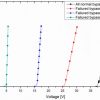
Figure 6 shows that as the number of damaged bypass diodes in a module increases, the lower the voltage required to produce high-intensity reverse current circulation. With just one damaged diode, reverse current already flows through the module at voltages slightly above 25 V.
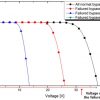
Figure 7 illustrates the current and voltage (IV) curves of the photovoltaic module with damaged bypass diodes. The open circuit voltage of the module is reduced from 30% to 90% according to the number of damaged diodes. This explains why reverse current circulation is potentially dangerous if there is any string with faulty modules.
The authors (SHIN et al., 2019) also evaluated the effect of failure of bypass diodes in strings through computational simulation and experiments carried out with 4 parallel strings, each with 15 modules.
Both in the simulation and in the field, experiments were carried out with the shading of some modules and with the defect situation of the bypass diodes – a situation obtained in the field by removing some modules from the string.
The results obtained with the strings confirmed the observations made with the modules, according to which reverse current will rarely flow in intact photovoltaic modules, in which the bypass diode has the possibility of coming into operation.
On the other hand, when there are modules with short-circuited bypass diodes, the voltage mismatches between the open-circuit strings become significant and allow the circulation of reverse current.
Conclusions
Several factors are decisive for the occurrence of dangerous reverse currents in solar plants: inverter shutdown, presence of defective bypass diodes and existence of many strings connected in parallel.
The PV system is less susceptible to reverse current when in operation and string currents flow to the inverter rather than circulating through the faulty string.
A fully shaded string in a photovoltaic array can suffer reverse current, as explained by (SPERTINO; AKILIMALI, 2009) and (VARGAS; GOSS; GOTTSCHALG, 2015) – however, this is a very rare condition.
Computational studies and experiments carried out in (SHIN et al., 2019) show that mismatches caused by irregular lighting conditions (partial shading) are not the cause of significant reverse currents in solar plants. The preponderant factor for the occurrence of reverse currents is the presence of defective bypass diodes.
The results presented in this article and other sources found in the literature (VARGAS; GOSS; GOTTSCHALG, 2015) corroborate the idea that no relevant reverse current occurs in photovoltaic systems in normal operation and with intact bypass diodes, even with partial shading.
References
- DHERE, NG et al. The reliability of bypass diodes in PV modules. Reliability of Photovoltaic Cells, Modules, Components, and Systems VI, v. 8825, p. 88250I, 2013.
- IEA-PVPS, R. Assessment of Photovoltaic Module Failures in the Field. [sl: sn].
- SHIN, WG et al. Current flow analysis of pv arrays under voltage mismatch conditions and an inverter failure. Applied Sciences (Switzerland), v. 9, no. 23, 2019.
- SMA. Reverse Current – Advice on generator configuration for PV systems using Sunny Mini Central. P. 1–3, 2009.
- SPERTINO, F.; AKILIMALI, JS Are manufacturing IV mismatch and reverse currents key factors in large photovoltaic arrays? IEEE Transactions on Industrial Electronics, v. 56, n. 11, p. 4520–4531, 2009.
- VARGAS, JP; GOSS, B.; GOTTSCHALG, R. Large scale PV systems under non-uniform and fault conditions. Solar Energy, vol. 116, p. 303–313, 2015.
- VINTURINI, M. Causes and effects of reverse current in photovoltaic modules, Canal Solar, 11/08/2019