SolarEdge Designer is photovoltaic system modeling and simulation software available free of charge on the internet.
The application is made available by SolarEdge, a manufacturer of inverters and power optimizers.
SolarEdge Designer is very similar to Helioscope, a well-known tool for photovoltaic system designers – but the latter is paid software.
The tool is accessible online, directly from the web browser, without the need to install software on your local machine.
The main function of the application is to allow you to quickly and intuitively model and simulate photovoltaic systems.
Power generation simulations are restricted to systems using SolarEdge inverters and optimizers, but it is also possible to use the software just to carry out photovoltaic module positioning studies, as we will show below.
The objective of this first article about SolarEdge Designer is to show how to access the tool, show how the roof of a residence is modeled and how the photovoltaic modules are distributed on the roof.
Access to SolarEdge Designer
To use the tool, you must access this address and create an account on the platform. SolarEdge.
You will need to provide some of your data, in a very quick process. You will then be directed to the screen where the Designer will be accessible, as shown in Figure 2.
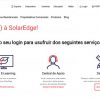
When you access the “Open Designer” option, the tool will open for you, as shown in Figure 3.
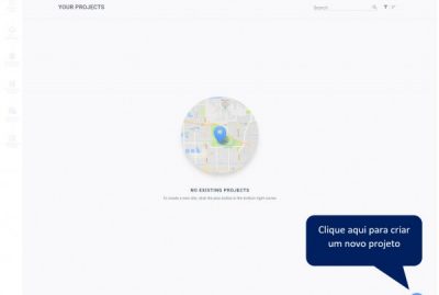
When entering the tool, the first message we receive is that there are no projects yet (NO EXISTING PROJECTS) and the system is waiting for the creation of our first project.
On the screen illustrated in Figure 3, you must click on the “+” sign to create a project.
Before taking the next step, we need to find out the location of the project. A very powerful feature of SolarEdge Designer is that it allows you to search for satellite images of the chosen location, simply by entering the geographic coordinates or the address of the installation.
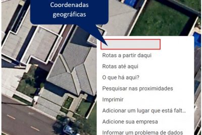
To find the geographic coordinates of the installation location, you can use tools such as “Google Maps”, as shown in Figure 4.
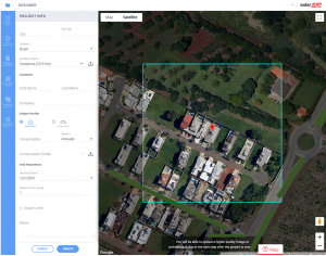
On the project creation screen, we will insert the obtained coordinates (Figure 5) and automatically obtain the satellite image of the installation location.
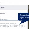
If you don't have the location's coordinates, you can search for the address directly in SolarEdge Designer, without having to use Google Maps.
Figure 6 shows the result of the search for the installation location, which in this case occurred based on already known geographic coordinates.
The next step is to enlarge the image using the “+” and “-” buttons located in the lower right corner of the screen.
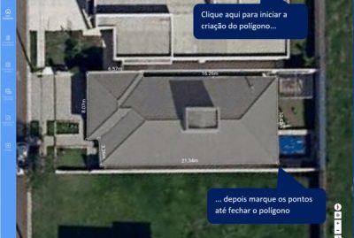
Next, you must create a polygon that delimits the roof. Polygon creation is accessible from the icon shown in Figure 7.
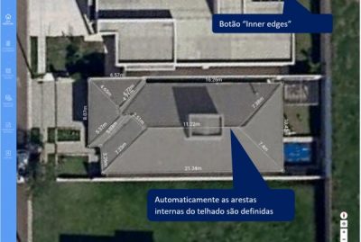
Don't worry about drawing the internal elements of the polygon to define the roof's waters. SolarEdge Designer will do this automatically for you, just click on the “Inner edges” button, shown in Figure 8.
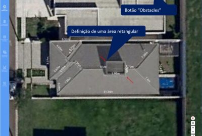
The roof where we are going to implement our photovoltaic system has a water tank. It is important to define this object as it will restrict the area for placing the photovoltaic modules and will also be an object that causes shadows, which will affect energy generation.
Figure 9 shows the definition of the object with the “Obstacles” tool. A rectangle is defined with two points demarcated.
This rectangle is just a surface and the drawn object has not yet become a volume. The definition of the volume (with dimension information on the “z” axis) will be done in the three-dimensional view of the model, as we will see below.
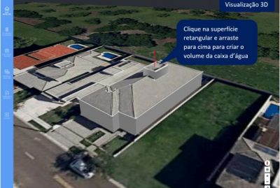
To define the vertical dimension (height) of the water tank, we will access the 3D visualization, as shown in Figure 10, and then create the volume.
To create the volume, we click on the rectangular surface and drag it upwards, holding the mouse.
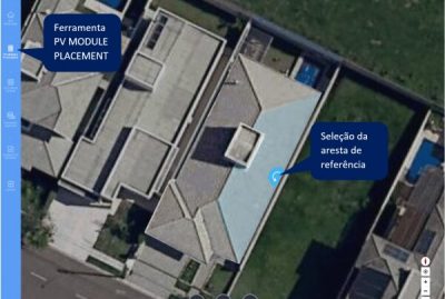
Finally, we are ready to insert the photovoltaic modules into the roof. Click on PV MODULE PLACEMENT (in the vertical bar on the left).
Then choose the area where you want to insert the modules and click on the edge that will be chosen as a reference, as shown in Figure 11.
After selecting the reference edge, a table opens containing information about the modules that will be inserted: inclination, azimuth, spacing, position (portrait or landscape). The first two parameters are automatically defined based on the roof characteristics.
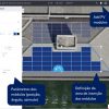
To start positioning the modules, you must access the “Add PV modules” option and define a rectangular area on the chosen surface, as shown in Figure 12. SolarEdge Designer will automatically position the modules, according to the available space.
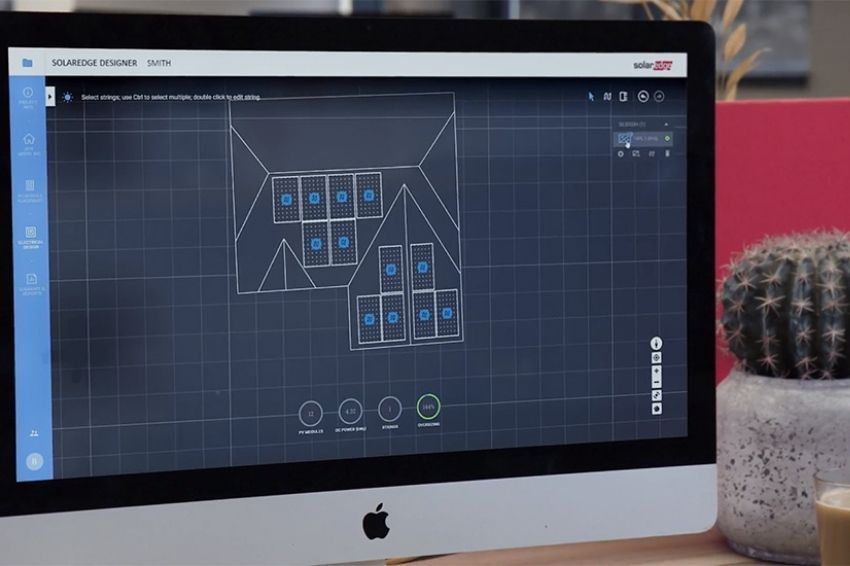
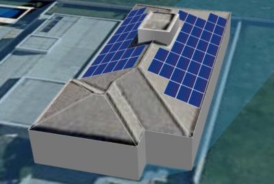
Once finished, we can obtain a 3D view of the project with the modules positioned. A beautiful image to show your client.
Conclusion
In this article we learn how to model a photovoltaic system, including the geometric definition of the roof and the positioning of the photovoltaic modules.
In the next articles in this series we will cover the electrical characteristics of the project, the study of shadows and the simulation of energy generation.


One Response
This class is very good, I would like to get this tool