
Updated October 15, 2025
Did you know that inverter shutdowns due to voltage fluctuations are one of the most common problems in photovoltaic systems? This type of failure usually occurs precisely when generation levels reach high levels, typically on sunny days, when the system should be operating at maximum efficiency.
In this article, you will understand why the inverter trips due to voltage fluctuations, which factors in the electrical grid influence this behavior, and what precautions must be taken in the electrical design to avoid generation losses and ensure the good performance of the solar plant.
The root of the problem lies in the quality of the electrical grid to which the inverter is connected. Installing a photovoltaic system requires care not only in the components and connections of the inverter, modules and the string box.
The designer also needs to be careful about what is after the inverter. The energy generated needs to leave the inverter and be injected into the connection point without causing disturbances to the electrical grid, both within the property and in the distribution network.
The main disruption to the electrical grid caused by photovoltaic systems is voltage surges. This variation is normal and, in many cases, goes unnoticed. However, when the electrical grid is fragile (or very precarious) or poorly dimensioned, the voltage variation can exceed the voltage and operating limits programmed into the inverter, causing it to shut down.
Understanding the problem
Electrical conductors have electrical resistance. When an electrical current passes through them, this resistance causes a voltage drop. Due to the voltage drop, in a home or in any electrical installation, the voltage obtained at the distribution panel will be lower than the voltage delivered by the utility company at the entrance pole.
When the installation's consumption increases, the voltage drop intensifies and the value of the electrical voltage available in the distribution panel may fall even further depending on how the installation was dimensioned.
In electrical installations, the voltage at the point of consumption will generally be lower than the voltage at the input pole due to voltage drops. In very poorly sized installations (which are not uncommon), the voltage drops will be more pronounced. But this is a problem that existed even before the advent of photovoltaic systems. What changed then?
In weak electrical networks, due to poor cable sizing, the voltage available for internal loads will always be reduced by the current flowing through the circuit. The more current circulating through the installation, the greater the voltage drop.
With the injection of energy by the inverter, the electric current present in the circuit can decrease in intensity or even be zeroed (when solar generation is equal to internal consumption), causing the voltage drop to decrease, which causes the voltage at the connection point (where the inverter is connected) to rise.
When solar generation is very large, the amount of energy injected by the inverter can generate a current in the opposite direction, when energy is exported to the utility company.
In this case, the voltage at the injection point will be higher than the input voltage provided by the utility, and in some cases may exceed the operating limit for which the inverter is programmed.
Enjoy to know the articles of the Canal Solar, as they share valuable insights into the renewable energy market. Don't miss out on these contents!
A little theory: resistance and impedance
Conductive materials have an internal resistance that depends on the metal used (copper or aluminum), the cross-section (cable gauge) and the length of the cable.
The longer the cable, the greater its resistance. The smaller the cable gauge, the greater the resistance. A very thin conductor makes it difficult for electric current to pass through, so its resistance is greater.
Each material used in cable manufacturing has a unique characteristic called resistivity, which affects the cable's resistance. The resistance of an electrical conductor can be calculated using the formula:
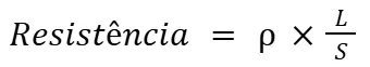
In the above formula, ρ is the resistivity of the material, L is the length of the cable, and S is its cross-section (area).
In short electrical circuits, resistance is the main cause of voltage drops. In longer circuits there are also voltage drops caused by reactances, which are the result of the capacitive and inductive effects present in electrical circuits.
A more complete model of a cable's characteristics involves factors such as the cable's capacitance and inductance. Capacitance and inductance are related to the distance between the cables, the voltage between them and the medium in which they are surrounded.
The sum of the effects of resistance, capacitance and inductance is called impedance. In cables that carry direct current, the effects of capacitance and inductance are null due to the very nature of electromagnetic effects.
In very long AC circuits, capacitance and inductance cannot be neglected, as their effects alter voltage drops and cable conduction losses. Impedance can also be significant in electrical connections.
Poorly made or inappropriate connections have significant impedance, which can even cause a loss of energy in the form of heating.
The cause of heating is the dissipation of energy over the electrical resistance of the contact. In addition to the resistance and impedance present in the cables, poor connections are also a major cause of voltage drops.
Voltage drop
When a current passes through an impedance in a circuit, there is a voltage drop between the positive and negative terminals of the impedance.
When taking into account that a real cable has a non-zero impedance, we can say that the passage of current in a cable also causes a voltage drop between its terminals. The voltage drop in a circuit caused by a real cable is determined below:
Since we are analyzing a two-conductor circuit, we must take into account the voltage loss in resistance across both cables. Therefore:
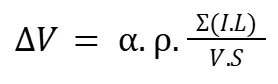
Where alpha = 2 for single-phase or two-phase circuits and 1,73 for three-phase circuits.
In commercial installations there are not many options for conductive materials, leaving the designer to choose between copper and aluminum. Circuit size also cannot always be adjusted freely, as there are physical and allocation demands on the devices.
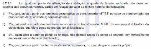
The most practical way to control the voltage drop in a circuit is to choose the cross section of the conductor. The standard for low voltage electrical installations – NBR 5410 – provides for a maximum limit on the voltage drop in a circuit, as shown below.
Grid-connected inverter
When connected to the power grid, the photovoltaic inverter receives at its terminals the voltage available at the connection point. If the inverter is connected directly to the consumer's input standard, the voltage at the connection point will be more stable (as it will depend only on the voltage drops existing in the electricity provider's distribution network circuit).
When the inverter is connected to a more internal point in the installation, the voltage at the inverter connection point may vary according to the voltage drops caused by the electrical currents present in the installation.
The voltage at the connection point can also vary depending on the intensity of the current injected by the inverter itself, as we discussed at the beginning of the article. If the inverter injects too much current, to the point of inverting the flow of energy, the voltage at the connection point will rise beyond the value found in the consumer's input standard.
However, there is a limit to the voltage at which the inverter can operate, which is defined by standard NBR 16149, as shown in the table below. The inverter voltage cannot be lower than 80% of the nominal supply voltage of the utility company. The inverter voltage also cannot be higher than 110% of the nominal supply voltage.
Each utility has a nominal supply voltage and the inverter must be parameterized according to this voltage. The voltage at which the inverter is authorized to operate is in the range between 80% and 110% of the nominal voltage of the distribution network, as shown in the table.
Table 1 – Export voltage limits for grid-connected inverters
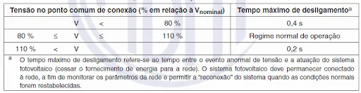
Therefore, if the inverter injects a lot of energy and if there are significant resistances (or impedances) in the installation, the voltage at the connection point may increase and exceed 110% of the nominal grid voltage, causing the inverter to automatically shut down.
This is a very common situation on big generation days. The inverter is switched off for this reason always occurs on days and times when solar radiation is most intense.
The photovoltaic system is disconnected at the moment when it should generate more energy – a very unpleasant situation that can be avoided with the correct design of the electrical installations (avoiding voltage drops) or with the parameterization of the inverter (changing its minimum and maximum operating limits , without violating the limits of standard NBR 16149).
Transformer impedance and voltage drop
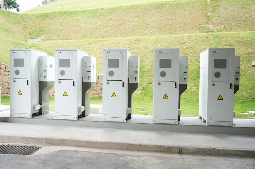
Larger solar photovoltaic systems are typically connected to the grid through a coupling transformer that raises the system's nominal voltage to the same utility level.
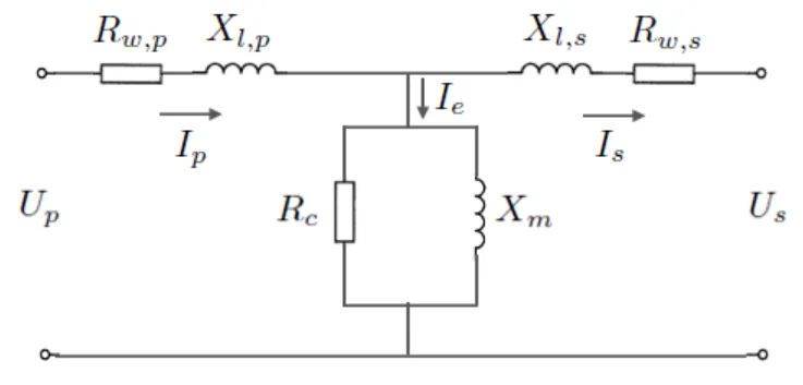
Transformers also have an internal impedance that can cause a voltage drop from the inverter's point of view. The equivalent circuit of a real transformer indicates the internal impedances of that device.
For a photovoltaic solar system to inject energy, the voltage on the side of the transformer facing the internal grid (secondary), represented by Us, must be within the operating range of the inverter, as explained in the previous section (i.e., between 80% and 110% of the utility's nominal supply voltage).
Inverter shutdown due to voltage drop
When an inverter is installed in a high-impedance circuit, i.e., a cable with an inadequate cross-section, poorly made connections or high-impedance transformers, the voltage at the connection point can be significantly high due to the impedance of the cable, poor contacts and to the presence of the transformer.
If the voltage increase is considerable, exceeding 110% of the nominal grid voltage (if the inverter parameterization is correct), the inverter will automatically shut down. This shutdown is a protection function present in inverters that in some cases causes unwanted shutdown of the equipment.
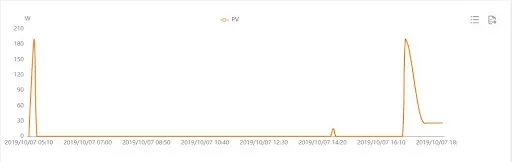
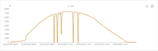
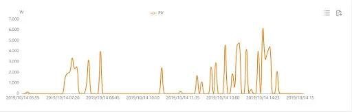
The inverter shutdown using the mechanism described above typically occurs at times of maximum generation – close to noon. These inverter shutdowns can be identified in the daily generation curves of the affected device, as shown in the example below.
Measures to overcome the problem
The first step to solving the problem is to check whether the voltage configured on the inverter is the same as the utility supply voltage, as the inverter must only operate within the limits established in Table 1.
The phenomenon described in this article is closely related to the impedance that the inverter sees on the AC side and, as shown previously, the sources of impedance seen by the inverter are: cables, connections and transformer.
Therefore, cables sized taking into account the voltage drop criteria described in the NBR 5410 standard minimize the risk of inverter shutdown due to voltage rise. As for connections, they must be well made, following current standards and periodically checked to ensure there is no looseness in the tightening.
If the internal impedance of the transformer or the cables that connect the photovoltaic plant's transformer to the utility's transformer are very high, the same reasoning applies as for the voltage drop in the cables.
To better understand how these factors impact your installation, access the Blog Canal Solar and discover valuable tips to optimize your photovoltaic system!
Deepen your knowledge
Functions and technical requirements of photovoltaic inverters


Answers of 9
See details on this topic here: https://tecseteletronica.blogspot.com/
I have a power plant to be installed on the local 127 V grid. However, the voltage drops in the afternoon on this grid... I wonder... can this power plant be installed without the problem of burning out the inverter?
You need to check if the voltage is within the limit specified by the NBR 16149 standard, which is up to 80% of the nominal voltage, which for a 220V network is 176V.
Coincidentally, after my neighbor installed solar panels on his house, the power on the street, including my house and that of other neighbors, has been going out almost daily, and the power goes out and comes back on a few seconds later, sometimes several times in a row. He generates energy and the excess is thrown into the power grid. Reading the article, I saw the part that talks about sunny days and I noticed that it is precisely on days of strong sun that this happens... could it be my neighbor's solar energy destroying the power grid on the street?
Hi Marcos. It's not possible to identify that; an analysis from the dealership is necessary.
In this case, I will measure the voltage at the inverter output and then at the connection point to the grid. The difference should be as minimal as possible.
Friend, my network has been disconnecting constantly, so just changing the 6mm cables to 10mm cables could help?
This can help if the cause is voltage drop, since larger cross-section cables can reduce the system's impedance.
Yes, but measure the mains voltages and check with the inverter manufacturer what the operating voltage range is.