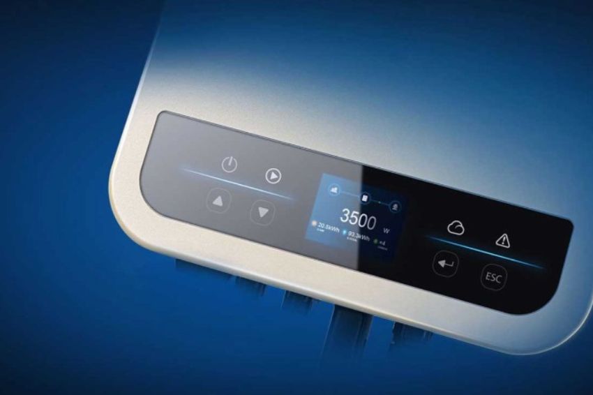
Currently, GE photovoltaic inverters are sold throughout the world market, and there are many doubts about the “Insulation failure” error message that the equipment emits when it is subjected to certain problems.
Given this, GE's solutions engineering team decided to develop this article explaining the reason for the error alert and what actions to take to find the problem.
Why does the inverter give an “insulation failure” alarm?
Insulation failure in GE inverters occurs when the inverter identifies that the impedance between the photovoltaic modules in a series (string) and ground is below the minimum values required by the inverter user manual.
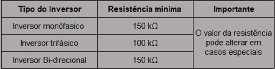
The table below has recommended minimum values.
-

Figure 1: Minimum resistance recommendation between PV series and grounding. Source: GE inverters
How to check the reason for the failure?
1) Using the inverter as test equipment (DC side)
To identify which of the photovoltaic series are presenting insulation failure problems, it is necessary to carry out an individual check of each string. A common approach is to isolate strings one at a time. Follow the steps below:
- Disconnect all photovoltaic series (strings) from the inverter;
- Connect only one string to the inverter at a time;
- Restart the inverter and observe whether the insulation fault persists.
If the inverter still shows insulation failure, it indicates that the connected string has insulation problems. If the insulation fault disappears and the inverter returns to normal operation, this indicates that the tested string is free of insulation problems.
Repeat this process for each of the photovoltaic series, isolating them individually. This way, it will be possible to identify which photovoltaic series or series are presenting the insulation failure. This approach allows for more accurate analysis and helps determine the problem in a specific PV array, making it easier to resolve the issue efficiently.
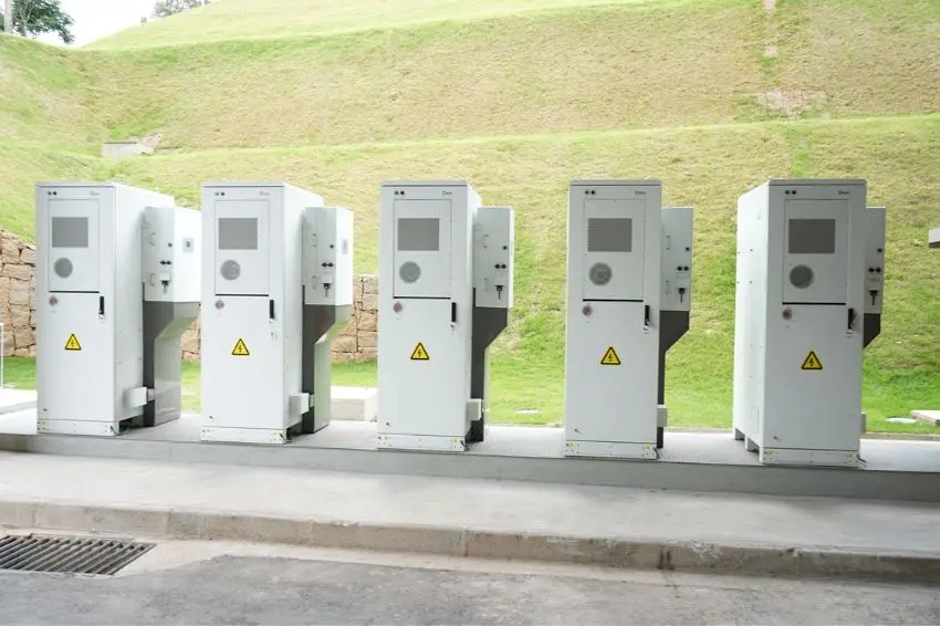
2) Using insulation testing equipment
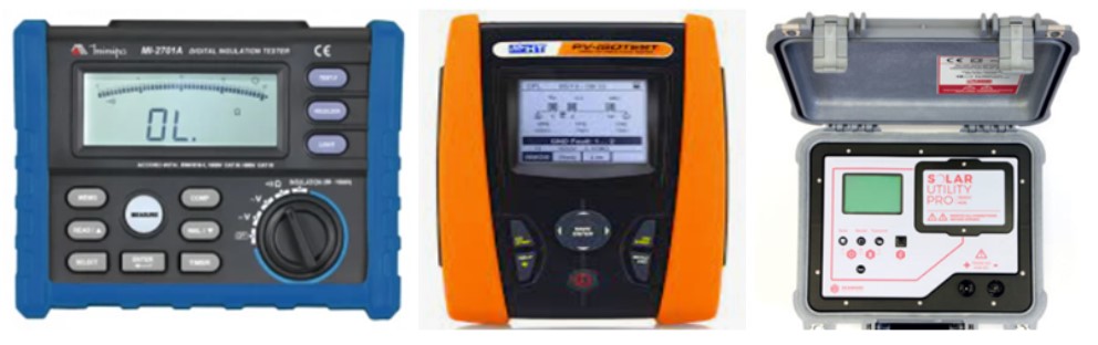
Another very common method is to use specific measuring equipment, such as a megameter, IsoTest or PV check, to locate the fault.
This equipment is designed to measure the insulation resistance of photovoltaic series individually. By measuring resistance, it is possible to accurately identify the presence of insulation faults in one or more strings.
-

Figure 2: Measuring instruments for measuring string insulation. Source: GE inverters
It is essential to highlight that these tests must be carried out by a qualified professional, who has knowledge and experience in operating this equipment.
Correctly interpreting results and making appropriate decisions requires specific technical skills.
By using this measuring equipment, it is possible to precisely locate the insulation failure in each string, allowing the necessary corrective measures to ensure the safety and adequate performance of the photovoltaic inverter.
3) AC side test
It is important to use a suitable multimeter to measure the voltage between the neutral cable and the ground cable on the AC (alternating current) side. The result of such a test must present values close to zero, indicating a correct connection and a good grounding system.
If the measurement shows a value greater than 10V, this may indicate a measurement error or a fault in the grounding system. In this case, it is recommended to review the connections of the inverter grounding system and strings so that they are properly installed and in compliance with applicable standards and regulations.
Problems solution
1) Checking the DC circuits
Statistically, most insulation failures in photovoltaic systems occur on the DC (direct current) side of the installation. Therefore, after identifying which string is presenting the problem, it is recommended to check the following items:
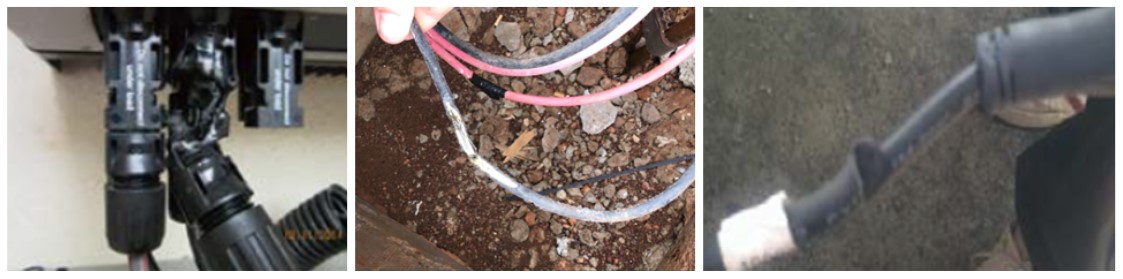
- DC connection between PV modules: Carefully check the electrical connections between PV modules in the affected string. Make sure the cables are correctly connected, without damage or looseness;
- DC connectors reaching the inverters: Check the DC connectors that are connected to the inverters, both at input and output. Check that the connectors are well fitted, with no damage or signs of poor contact. Also check that the connectors are clean and free from dirt or corrosion;
- DC cabling: Check the DC cabling of the affected string, from the photovoltaic modules to the inverter. Make sure the cabling is in good condition with no visible damage or excessive wear.
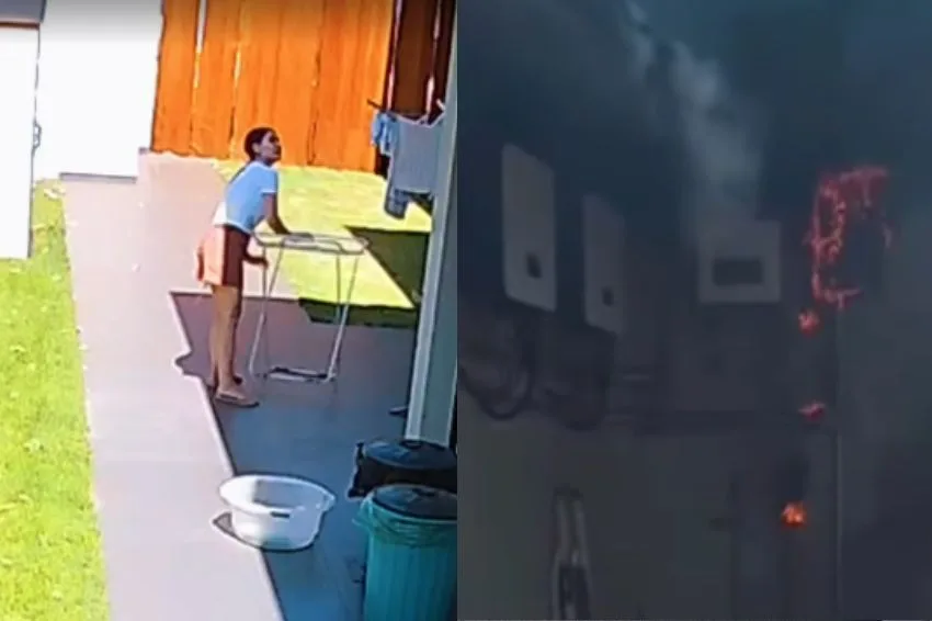
-

Figure 3: Problems that cause insulation failures. Source: GE inverters
2) Checking the grounding of the modules
In photovoltaic design, the grounding system can be complex and the grounding discontinuity affects the impedance on the DC side. To guarantee the integrity of the system, it is recommended to measure the continuity between the masses of the grounding system, checking whether all modules are equipotentialized.
This measurement helps identify discontinuities and ensure an efficient connection between components, minimizing the risk of insulation failures.
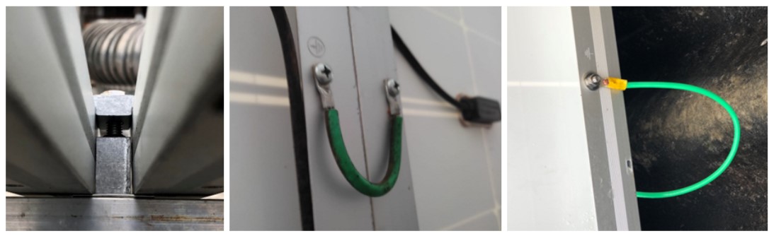
It is common for the structure of photovoltaic panels to be fixed using end and intermediate clamps. It is common for such clamps to use a clip to damage the anodization of the photovoltaic module frame and equipotentize them, ignoring the existing grounding holes in the panels.
Initially, the photovoltaic system can function normally, however, over time, the conduction capacity of the ground plate decreases, resulting in loss of grounding performance.
To ensure proper operation and safety, it is recommended to use the modules' grounding holes and connect them individually, thus avoiding grounding discontinuity.
-

Figure 4: Forms of equipotentialization of PV series. Source: GE inverters
3) DPS (Surge Protection Device) Check
The Surge Protection Device (SPD) is connected in parallel with the positive and negative leads of the DC circuits, providing a path for the surge current if it occurs.
Initially, the DPS can be considered as an open circuit between the poles (positive or negative) and ground. However, over time, it can deteriorate and this results in a decrease in impedance, which can lead to insulation failure.
If there is a circuit breaker on the DPS line, turning it off will allow you to remove the DPS from the PV system to check whether the error persists or not. This check helps identify whether the DPS could be causing an insulation failure or whether there is another source of the problem.
The closing thought
Insulation failures become more evident when the weather is humid and it is therefore common for the inverter to emit an alarm on rainy days or early in the morning. We recommend that you activate alarm notifications in the settings tab of the our portal so that you receive the information and can identify the problem as soon as possible.
Insulation failures are harmful to photovoltaic inverters and as they are a fundamental component of the photovoltaic system, it is important to maintain correct operation.
If you need help, GE's after-sales team is always available to help resolve problems, so we can guarantee your customer's normal energy generation. Contacts: +55 81 4042 1229 or support.br@gesolarinverter.com.
The opinions and information expressed are the sole responsibility of the author and do not necessarily represent the official position of the author. Canal Solar.