
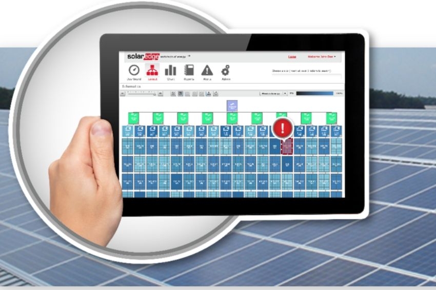
After installing the photovoltaic system, the anxiety about keeping up with energy generation and saving money is great. The customer and installer usually follow up every day, perhaps every hour for the first 30 days. Although the focus is on energy generation, monitoring provides a range of information that is just as important.
Mainly alarms, fault detection and analysis of loss of performance of a component or the entire system. Every photovoltaic system has monitoring, however, the monitoring of the system with string inverters “sees” the entire string without being able to detail module by module. For a photovoltaic system with optimizers, the monitoring can be much more detailed and facilitates the detection of faults, performance losses and alarms.
string system versus optimizers
The traditional photovoltaic system connects modules in series forming strings. The strings are connected into multi-string inverters, with one string per input.
Therefore, the monitoring, present in the inverter, can analyze the electrical characteristics per string. The photovoltaic system with optimizers connects each optimizer to one or two modules. Thus, it is possible to measure each optimizer, making monitoring much more detailed.


It can be seen in Figure 2 that the modules are not generating the same power at the time of the analysis. Whereas, in a system with strings, all modules would be limited by the one with the lowest generation. In this system, we have two modules connected by an optimizer.
It is possible to analyze the information at the same time from an optimizer with modules presenting low generation (24,1 W) and high generation (203,91 W). Figure 3 shows two curves for each optimizer analyzed: voltage and photovoltaic power. It is possible to notice an increase in voltage of the shaded module (MPPT correction) and a decrease in power.

With individual monitoring per optimizer, it is possible to observe how much each module is generating individually. And discover possible flaws by comparing them.
Performance below estimates
After installation of the photovoltaic system and the entire approval process with the concessionaire, when generation is lower than expected, the causes can be several: system sizing error, shadows, or just one module that affects all others connected in series.
String monitoring makes it difficult to detect problems in modules that affect the entire string. This problem can be caused either by an external factor, such as shadows or dirt, or internally, such as a failure in the module or in the case of a module with different characteristics than the others.
It is up to the installing company to find out what and where the problem is. And panel-level monitoring with greater detail of information would make the work much easier.
In the case of monitoring by the company SolarEdge, a manufacturer of optimizers and inverters, it is possible to compare, in addition to the generation for each year, the generation of the installation for a given month year by year.

Bypass diodes
Every module has bypass diodes installed during manufacturing, usually three. When a system failure occurs, one or more diodes may burn out. A burned out diode is easily detected by analyzing the operating or open-circuit voltage of a module. However, in a string, this voltage loss is masked by the high voltage level.
1 Example
A module with Voc = 45 V, presents a Vmpp = 36 V (in STC), with a burned bypass diode, presents a Voc = 30 V and Vmpp = 24 V. Figure 5 shows a real monitoring with each optimizer connected to two modules.

The voltage observed in one of the optimizers is 17% lower than the voltage in the others. As a comparison, if there were two strings with ten modules each and one of them had a burned bypass diode, the operating voltage of this string would be 4% lower than the other, an almost imperceptible difference.
Note: it is interesting to note in figure 5 the variation in the Vmp value during the day, the value decreases to 64 V with the increase in temperature and returns to 70 V at the end of the day.
2 Example
Two strings, with ten modules of 330 Wp each, generate energy during a certain day, reaching a peak of 2.350 W around noon. If one of them has a burned bypass diode, the difference in the generation curves would be minimal.
If these twenty modules were connected to ten optimizers, the difference in generation curves would be much more noticeable. Figure 6 shows the generation curves for strings and optimizers.

PID
O PID effect (Potential Induced Degradation) causes an inevitable loss of power in photovoltaic modules every year. This loss may be greater or lesser in different modules even if they are from the same manufacturer.
In a string, all modules work limited by the one with the lowest power, and in classical monitoring it is impossible to understand the loss due to the PID effect. Since monitoring in optimizers shows module by module, it is possible to observe the evolution of the PID effect in different modules. Figure 7 shows different power values generated in the same installed system due to the PID effect.

References
- [1] IV Curve Tracing vs. SolarEdge Real Time Monitoring. SolarEdge Technologies. Version 1.0. April, 2019.
- [2] Handelsman, Lior. Optimize your O&M Procedures with Optimized Management of your PV system – Implementing a PV plant supervision system to reduce Operation and Maintenance (O&M) costs and increase profitability.


Comments
Comments are moderated before publication.Comments should be respectful and contribute to a healthy debate. Offensive comments may be removed. The opinions expressed here are those of the authors and do not necessarily reflect the views of the author. Canal Solar.