
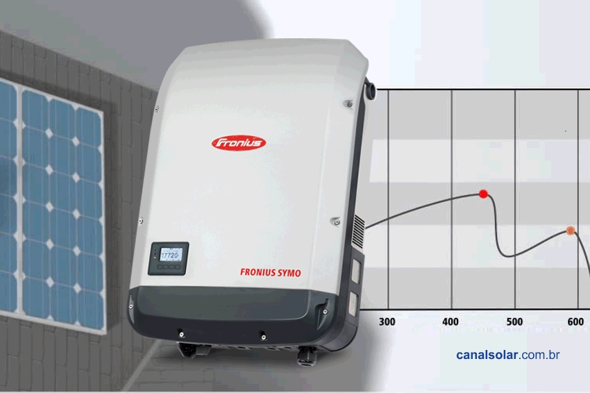
In this article, we will discuss a very interesting solution for reducing losses caused by shading of photovoltaic modules. If you have read my previous articles, you will already know that partial shading is a major danger for photovoltaic systems. Few people know this.
Most photovoltaic system designers are unaware of (or ignore) the problem of partial shadows. And most of the consumer market is unaware of the differences between inverters.
When there are no shadows – a rare situation in residential photovoltaic systems – everything works well and it is difficult to notice the differences between inverters from different manufacturers, but not all inverters are capable of providing maximum energy generation in shady situations. This is a very delicate subject that I intend to explain in detail below.
IV curve of photovoltaic modules and arrays
Let's take a quick look at the characteristic curves of photovoltaic modules. Photovoltaic modules have an electrical behavior that is described by their current and voltage curve (IV). The product of the voltage and current gives rise to the power and voltage curve (PV).
If you have a module, a string (modules connected in series) or an array (several strings connected in parallel), there will always be equivalent IV and PV curves, as shown in the illustrations below.


-

Figure 1: IV and PV curves of a module, a string and a photovoltaic array

The IV and PV curves of photovoltaic modules, strings or arrays would always have the same shape if the modules in an installation were always subjected to the same light intensity. We know that this is not always true.
This can happen in solar plants, but in rooftop installations, especially in urban areas, the situation is quite different. A single string or a single shaded module can bring down the power generation of an entire system.
-

Figure 2: IV and PV curves of strings with uniform and partial shading

In Figure 2 we see what happens when only some modules of a string are shadowed. This is what we call partial shadowing. The same situation can be found in systems with several strings in parallel, even if only one of the strings has a small portion of the modules shadowed.
The problem highlighted in Figure 2 is the presence of several maximum power points on the IV and PV curves, a phenomenon that occurs in situations of partial shading of the photovoltaic modules of a system. On the IV curve, the maximum power point is located at the knee of the curve, while on the PV curve, the maximum power point is located at the peak of the graph.
But what is the problem caused by the presence of multiple maximum power points? To understand this, it is necessary to understand how the photovoltaic inverter works. There is a control system in every photovoltaic inverter called MPPT (maximum power point tracker).
What does MPPT do?
When we connect a set of modules to the inverter input, respecting the characteristics of the equipment, it does not know how many or which modules are connected.
The inverter has no knowledge of the module model, power, number of connected modules and series. The only thing the inverter knows is that it must extract energy from the modules and convert it into alternating current.
The photovoltaic module has an optimal operating point that is its maximum power point, located at the knee of the IV curve or at the peak of the PV curve. One of the functions of the photovoltaic inverter is to adjust the operating point of the modules, making them operate as close as possible to their maximum power point.
Since the inverter does not know the characteristics of the modules connected to it, there must be some way to track the maximum power point. This is the function of the MPPT system found in all grid-tie solar inverters, used in photovoltaic systems connected to the electricity grid.
The MPPT system allows searching for the maximum power point of the photovoltaic module (or set of modules) through small disturbances. The inverter increases the operating voltage of the modules a little and observes what happened.
If the power has increased, it continues to increase even more. If the power decreased in the first disturbance, then the algorithm instructs the inverter to move in the opposite direction, decreasing the voltage to observe whether the power will increase or decrease.
This simple method, called disturbance and observation, is used in almost all grid-tie solar inverters. The idea behind the algorithm is to cause slight disturbances in the voltage of the modules and observe what happens as a result. In this way, the inverter tracks the IV and PV curves in search of the maximum power point.
-

Figure 3: Operation of the “disturbance and observation” MPPT algorithm with a normal PV curve (without shadows or with uniform shadowing). The inverter increases the operating voltage of the modules. If the power decreases, it returns to the previous point. Likewise, if the power decreases when the voltage decreases, the MPPT returns the operation to the same point. With this method, the inverter can locate the maximum power point of the module, string or photovoltaic array.

-

Figure 4: MPPT algorithm tied to a local maximum in a situation of partial shading of photovoltaic modules

The disturbance and observation algorithm works very well when all modules have the same light intensity. In this case, the inverter will be able to find the maximum point or peak of the PV curve. However, in partial shading situations, most inverters will not be able to find the maximum power point of the system because there are several maximums, as illustrated in Figure 4.
In this example, there is a global maximum (which would be the optimal operating point of the system) and a local low-power maximum. In cases such as the one illustrated in Figure 4, which occur in partial shading situations, the MPPT mechanism will almost always be stuck at some local maximum point, being unable to see the existence of the global maximum.
What does this mean in practice? In simple terms, you can have a 10 kW system that will only deliver 300 W because of a single shaded module. There must be a way to protect ourselves from partial shade, which is a very common situation in PV systems. What can we do?
There are several strategies, which include separating modules into smaller sets, adopting microinverter technologies and optimizers or the use of inverters with algorithms Smart or dynamic MPPT.
What is dynamic MPPT?
Dynamic MPPT is the generic name given to a set of strategies that can be used to improve the performance of traditional MPPT algorithms. There are several techniques in the literature for performing dynamic MPPT and a few inverter manufacturers employ these methods in their equipment.
The dynamic name suggests that the algorithm does not have static and repetitive operation. Contrary to traditional algorithms, dynamic MPPT changes its operating mode over time, which allows tracking of maximum global power in situations of partial shading, when the photovoltaic system has one or more local maxima or peaks.
Dynamic MPPT has its drawbacks, so it should be used with some moderation. A very dynamic algorithm (very fast) can cause disturbances in the operation of the inverter, which can lead to the opposite effect of reducing efficiency. An algorithm that is too slow can be ineffective, almost as bad as a traditional MPPT.
The world's leading inverter manufacturers, who invest a lot of effort in research and development, are able to offer the market inverters with sufficiently good (and moderately fast) dynamic MPPT algorithms, capable of facing some very complex shading situations, which would simply be ignored by inverters. conventional.
It is not the purpose of this article to go into an in-depth discussion about the operation and theory involved in dynamic MPPT algorithms. But let's at least try to understand a little of what we are talking about. The central idea of any MPPT algorithm is to cause disturbances in the voltage of the photovoltaic modules, trying to observe what happens to the power of the modules (whether it decreases or increases) after each disturbance.
Based on the result of the disturbances (increase or decrease in power), the algorithm can determine whether it is disturbing in the right or wrong direction. This disturbance and observation procedure is illustrated in Figures 3 and 4. The main idea of dynamic algorithms is to perform, from time to time, some disturbances that are slightly larger than normal. Then, the inverter slowly increases the size of the disturbances and checks what happens.
With this, the MPPT algorithm is able to realize that it was stuck at a local maximum when at some point it observes that the power has increased when in fact it should have decreased. At this point, the algorithm abandons the local maximum (to which it was initially stuck) and sets out in search of its maximum objective: the global maximum or peak of the PV curve of the photovoltaic system, the operating point at which the energy generation of the photovoltaic system will be maximized.
-

Figure 5: Operation of the MPPT algorithm with dynamic peak manager function. The algorithm is able to escape the local maximum and is able to find the global maximum of the power curve of the photovoltaic system, ensuring maximum energy generation even in a partial shading condition as illustrated in the figure.

Test results
We tested a Fronius Symo inverter in LESF (Energy and Photovoltaic Systems Laboratory) at UNICAMP. The inverter was connected to an electrical grid simulator, as equipment is not normally connected directly to the electrical grid in laboratories.
In this case, we could have even used the electrical grid directly, as our interest was only in testing the MPPT system. The electrical network simulator is useful when we want to carry out tests on the AC (alternating current) side of the inverter, producing electrical network disturbances (variations in frequency, voltage, harmonic distortion) to verify the behavior of the inverter in different power quality scenarios. electricity.
The most important piece of equipment (after the inverter) in the tests we perform is the photovoltaic module simulator. We use a Terra SAS (solar array simulator) from Ametek, one of the most powerful pieces of equipment on the market.
This equipment is capable of faithfully reproducing the behavior of a set of photovoltaic modules. This makes it possible for us to test a solar inverter without having a solar plant on the roof.
It would be great to have a solar plant at our disposal to perform tests, but a real photovoltaic system would not allow us to perform specific tests, nor would it allow us to reproduce the same tests over and over again. If the goal is to test inverters, the best resource we can have at our disposal is a photovoltaic panel simulator like the one shown in the photo below.
-

Figure 6: Inverter test bench at LESF – Energy and Photovoltaic Systems Laboratory at UNICAMP – with the Fronius Symo inverter, which has the DPM – dynamic peak manager feature

-

Figure 7: SAS photovoltaic module simulators – solar array simulator. Each of these devices is capable of reproducing the behavior of photovoltaic arrays of up to 15 kW

We have configured our SAS (solar array simulator) to reproduce some situations of uniformly and partially shaded PV strings. The IV and PV curves of these strings are shown below. The figures below are screenshots of the SAS simulator control software.
-

Figure 8: Examples of IV and PV curves produced with the SAS simulator, reproducing different situations: without shade, with many shaded panels and with few shaded panels. In the first case we notice the existence of a single peak in the power curve. In the following two cases we find, respectively, curves with 5 and 3 peaks, which represent a great challenge for the inverters' MPPT algorithms.

We tested the Fronius Symo inverter with DPM in two different cases. The first case, illustrated in Figure 9, presents a PV curve with three peaks. In this case, we observed that the result was very good. First, the inverter tracked peak 1. This is because the inverter always starts tracking the PV curve from the maximum voltage (voltage and open circuit). Any inverter we were testing would be able to find peak 1.
A conventional inverter (without the DPM) would remain forever stuck at peak 1, without seeing the existence of peak 2, with greater power. After a few moments at peak 1, with a power of 3,2 kW, the Fronius Symo inverter was able to escape this situation and locate peak 2, with a power of 6,8 kW.
See how great the loss of this photovoltaic system would be with a conventional inverter: the operating power practically doubled with the presence of the dynamic peak manager.
-

Figure 9: Operation of the DPM – dynamic peak manager – of the Fronius Symo inverter on a curve with two power peaks. Initially, the MPPT tracks peak 1 and after a few moments locates peak 2. An inverter with conventional MPPT would not be able to locate peak 2, keeping the PV system operating at peak 1, which would represent a large loss of generation.

In the second case, illustrated in Figure 10, we pose an even greater challenge to the inverter: a PV curve with three peaks. Once again the Fronius Symo inverter did very well, being able to locate peaks 1, 2 and 3 sequentially.
The yellow arrows in Figures 9 and 10 show the instantaneous operating points of the photovoltaic system. The photos were taken at different times, showing situations that occurred before and after. It is interesting to see the dynamic peak manager in action on video.
-

Figure 10: Operation of the DPM – dynamic peak manager – of the Fronius Symo inverter in a curve with three power peaks. Initially the MPPT tracks peaks 1 and 2. After a few moments it locates peak 3. An inverter with conventional MPPT would not be able to locate peak 2, maintaining the operation of the photovoltaic system at peak 1 or peak 2, which would represent a great loss of generation.

Conclusions
PV systems run the risk of operating at low power levels in partial shade situations, when the inverter's MPPT is not capable of detecting local power peaks. Only inverters equipped with dynamic MPPT algorithms are capable of providing maximum PV system performance during partial shade situations, when only part of the modules in a string or array are covered by shadows.



Comments (2)
Comments are moderated before publication.Comments should be respectful and contribute to a healthy debate. Offensive comments may be removed. The opinions expressed here are those of the authors and do not necessarily reflect the views of the author. Canal Solar.
Excellent!
I'm preparing my TCC and I hadn't read any scientific article yet and I also didn't know about the existence of equipment that performs the dynamic search for the MPPT. Thank you very much for the great information!
Very good article, congratulations. Would you be able to report the behavior to other inverter manufacturers?